Federal Signal Corporation Informer15 Installation, Operation And Service Manual
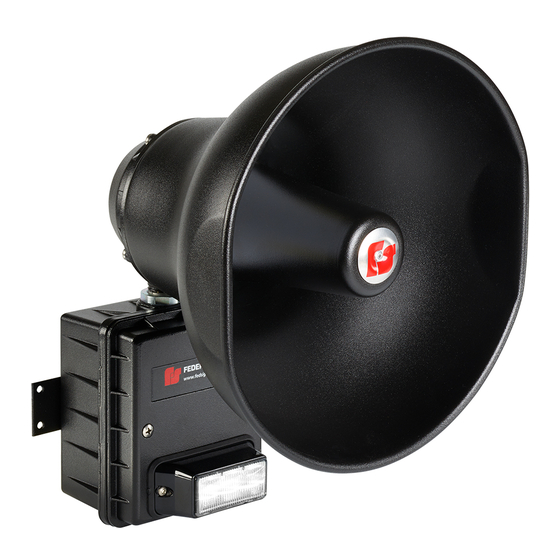
Ip-enabled indoor/outdoor speaker
Hide thumbs
Also See for Informer15:
- Description, specifications, installation, operation, and service manual (20 pages) ,
- Manual (12 pages) ,
- Setup, configuration, and operation manual (20 pages)
Table of Contents

Related Manuals for Federal Signal Corporation Informer15


Summary of Contents for Federal Signal Corporation Informer15
- Page 1 Informer15 Speaker ™ Model I-IP15 IP-Enabled Indoor/Outdoor Speaker Description, Specifications, Installation, Operation, and Service Manual 25500494 Rev. A0 0918 Printed in U.S.A. © Copyright 2018 Federal Signal Corporation...
- Page 2 A copy of this limited warranty can also be obtained by written request to Federal Signal Corporation, 2645 Federal Signal Drive, University Park, IL 60484, email to info@fedsig.com or call +1 708-534-3400.
-
Page 3: Table Of Contents
Wiring to the Control Board ..........................13 Closing the Housing ............................15 Operations................................16 Testing ..................................17 Maintenance ................................18 Ordering Replacement Parts ..........................18 Getting Service ..............................18 Figures Figure 1 Depth and Height of Informer15 Speaker .....................12 Figure 2 I-IP15 Controller Board ..........................15 Description, Specifications, Installation, Operation, and Service Manual... - Page 4 Table 5 Connectors and Jacks for Control Board ....................16 Table 6 Connectors and Jacks for Amplifier .......................16 Table 7 Visual Indications for Control Board ......................17 Table 8 Visual Indications for Amplifier .......................17 Table 9 Replacement Parts ...........................18 Informer15 Speaker (Model I-IP15)
-
Page 5: Safety Messages
• When Informer15 Speakers are used out of doors, people indoors may not be able to hear the warning signals. Separate warning devices or procedures may be needed to effectively warn people indoors. - Page 6 For optimum sound distribution do not install this speaker where objects would block any portion of the front of the Informer15 Speaker. • Do not paint the Informer15 Speaker. No finish or coating is required. Paint may obstruct the sound output, reducing the effectiveness of the horn. •...
- Page 7 To reduce the risk of electric shock, do not perform any servicing other than what is contained in the operating instructions unless you are qualified to do so. Refer all servicing to qualified service personnel. Always test the Informer15 Speaker before using after repairs have been made.
-
Page 8: General Description
The Informer15 can be programmed and configured as a standalone device to only use the inputs to activate the Informer15. This may be useful if the location has no network connectivity, but where voice and tone alerts from locally activated inputs is required. -
Page 9: Features
General Description Features The Informer15 has the following features; some features require the use of the Commander software system: • Outdoor or indoor IP-enabled speaker for audible and visual alerts • Speaker rated at 112 dB for tones and 107 dB for pink noise at 10 feet •... -
Page 10: Ordering Information
Hum and Noise < -45 dB Input Levels 1.77 Vrms (5 Vpp), 10 Vrms (28.3 Vpp) and 25 Vrms (70.7 Vpp) Table 3 Environmental Operating temperature range -30°C to +65°C/-22°F to +149°F Humidity range 0-95%, non-condensing Informer15 Speaker (Model I-IP15) -
Page 11: Installation
Speaker Cone Tip and Projector Spun aluminum alloy with powder coated finish. Installation Read and adhere to all safety warnings in this manual before installing the Informer15 Speaker. Electrocution or severe personal injury can occur when making electrical connections, drilling holes, or lifting equipment. Therefore, experienced... -
Page 12: Flat Surface Mounting
13/64-inch diameter holes and secure the unit with #10 screws, lock washers and nuts. 4. Route wires through the 1/2-inch threaded openings into the Informer15 Speaker unit in accordance with National and Local Electrical codes. -
Page 13: Opening The Housing
Wiring to the Control Board To wire the Control Board: 1. If networking the Informer15 to Commander, use the LAN interface to provide both IP communication and PoE from the switch. The Informer15 Speaker has an 8 pin Ethernet port for connecting to the network. - Page 14 Once the unit is configured and tested, place a shorting jumper across pins 1 and 2 of JP8, OPTION 1. To configure the Informer15 Speaker, use Commander software version 15.4 or later. See the Informer Setup and Programming Manual.
-
Page 15: Closing The Housing
1. Verify that the cover gasket is in the groove around the perimeter of the rear cover. 2. If the front of the unit was removed, install the visual indicator cable and attach the cover to the Informer15 Speaker. Property damage, serious injury, or death could occur if the housing is not closed properly. -
Page 16: Operations
Amplifier to Controller Interface Pin1 (-) Speaker output Pin2 (+) Speaker output Amplifier Gain (For max volume, turn clockwise.) The following indicators are for troubleshooting purposes only. These indicators are not visible when the unit is closed. Informer15 Speaker (Model I-IP15) -
Page 17: Testing
Testing Table 7 Visual Indications for Control Board Power Digital Input 1 active Listen Talk Digital Input 2 active Network connected CPU running Digital Input 3 active Digital Input 4 active D19 Relay Output active Table 8 Visual Indications for Amplifier Power LED ARM LED Testing... -
Page 18: Maintenance
NEC guidelines and local codes. • Never alter these units in any manner. Note, additional openings or alterations made to the Informer15 Speaker may jeopardize the safety of the hazardous location. • The nameplates, which contain cautionary or other information of importance to maintenance personnel, should not be obscured if the exterior of device is painted. - Page 19 2645 Federal Signal Drive University Park, Illinois 60484-3167 www.fedsig.com Customer Support 800-548-7229 • +1 708 534-3400 Technical Support 800-524-3021 • +1 708 534-3400...
- Page 20 2645 Federal Signal Drive University Park, Illinois 60484-3167 www.fedsig.com Customer Support 800-548-7229 • +1 708 534-3400 Technical Support 800-524-3021 • +1 708 534-3400...
Need help?
Do you have a question about the Informer15 and is the answer not in the manual?
Questions and answers