Table of Contents
Advertisement
Quick Links
INSTALLATION AND MAINTENANCE INSTRUCTIONS
XP6-R Six Relay Control Module
SPECIFICATIONS
Normal Operating Voltage:
Stand-By Current:
Alarm Current:
Temperature Range:
Humidity:
Dimensions:
Accessories:
Wire Gauge:
Relay Current:
RELAY CONTACT RATINGS:
CURRENT RATING
2 A
3 A
2 A
0.46 A
0.7 A
0.9 A
0.5 A
0.3 A
All relay switch contacts are shipped in the standby state (open) state, but may have transferred to the activated (closed) state during shipping. To ensure that
the switch contacts are in their correct state, modules must be made to communicate with the panel before connecting circuits controlled by the module.
BEFORE INSTALLING
If the modules will be installed in an existing operational system, inform the
operator and local authority that the system will be temporarily out of service.
Disconnect the power to the control panel before installing the modules. This
system contains static sensitive components. Always ground yourself with a
proper wrist strap before handling any circuits so that static charges are re-
moved from the body. The housing cabinet should be metallic and suitably
grounded.
NOTICE: This manual should be left with the owner/user of this equipment.
GENERAL DESCRIPTION
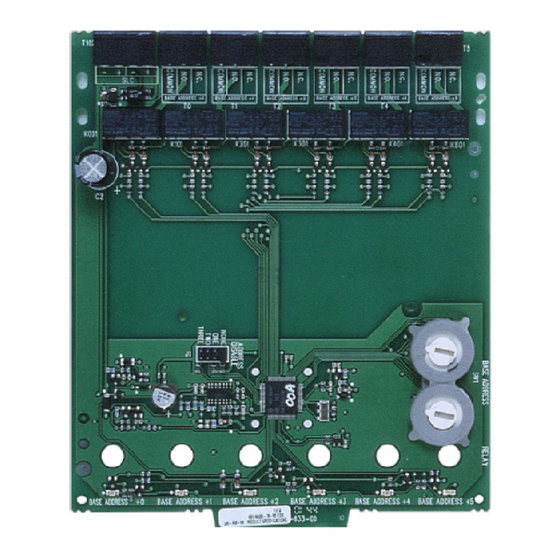
The XP6-R Six Relay Control Module is intended for use in an intelligent alarm
system. Each module is intended for Form-C switching applications, which
do not require wiring supervision for the load circuit. A single isolated set
of dry relay contacts is provided for each module, which is capable of being
wired for either normally open or normally closed for each operation. Each
module has its own address. A pair of rotary code switches is used to set the
address of the first module from 01 to 154. The remaining modules are auto-
matically assigned to the next five higher addresses. Provisions are included
for disabling a maximum of three unused modules to release the addresses to
be used elsewhere. Each XP6-R module also has panel controlled green LED
indicators. The panel can cause the LEDs to blink, latch on, or latch off.
N500-78-00
15-32VDC
1.90 mA @ 24V
32 mA (assumes all six relays have been switched once and all six LEDs solid on)
32°F to 120°F (0°C to 49°C)
10 to 93% Non-condensing
6.8˝H × 5.8˝W × 1.0˝D
CHS-6 Chassis; BB-25 Cabinet; BB-XP Cabinet; CAB-3 Series Cabinets; CAB-4 Series Cabinets
12-18 AWG
30 mA/Relay Pulse (15.6 mS pulse duration) pulse under panel control
MAXIMUM VOLTAGE
25 VAC
30 VDC
30 VDC
30 VDC
70.7 VAC
125 VDC
125 VAC
125 VAC
WARNING
LOAD DESCRIPTION
PF = 0.35
Resistive
Resistive
(L/R = 20ms)
PF = 0.35
Resistive
PF = 0.75
PF = 0.35
CONTENTS INCLUDE:
(6) 1 × 3 Terminal Blocks
(1) 1 × 4 Terminal Blocks
(2) 11/4˝ (32mm) Stand offs
(4) Machine Screws
(2) Nuts
(1) Shunt (NOTE: For the disable position, not more than one shunt shall be
installed at the same time)
COMPATIBILITY REQUIREMENTS
To ensure proper operation, this module shall be connected to a compatible
Notifier system control panel.
COMPONENTS
Following are descriptions of the XP6-R mounting frameworks. There are two
mounting options for XP6-R modules:
• Up to six XP6-R modules can be installed on a CHS-6 in a CAB-3, CAB-4
or BB-25 cabinet
• One or two XP6-R modules can be installed in a BB-XP cabinet
Chassis
The CHS-6 chassis is used to mount XP6-R modules in a BB-25, CAB-3 or
CAB-4 Series cabinet. It accommodates up to six XP6-R modules in a single
cabinet row three modules wide and two modules deep.
1
12 Clintonville Road
Northford, CT 06472-1653
Phone: 203.484.7161
APPLICATION
Non-coded
Non-coded
Coded
Non-coded
Non-coded
Non-coded
Non-coded
Non-coded
I56-1804-012
Advertisement
Table of Contents

Related Manuals for Honeywell Notifier XP6-R


Summary of Contents for Honeywell Notifier XP6-R
- Page 1 INSTALLATION AND MAINTENANCE INSTRUCTIONS 12 Clintonville Road XP6-R Six Relay Control Module Northford, CT 06472-1653 Phone: 203.484.7161 SPECIFICATIONS Normal Operating Voltage: 15-32VDC Stand-By Current: 1.90 mA @ 24V Alarm Current: 32 mA (assumes all six relays have been switched once and all six LEDs solid on) Temperature Range: 32°F to 120°F (0°C to 49°C) Humidity:...
- Page 2 2. Chassis Installation FIGURE 1. CHS-6 CHASSIS: The CHS-6 chassis is mounted in the BB-25, CAB-3 or CAB-4 Series cabinets. It is shipped with two self-threading screws, which are used to fasten the chassis to the back wall of the cabinet (see Figure 4). FIGURE 4: MOUNTING THE CHS-6 CHASSIS MOUNT WITH SELF-THREADING SCREWS...
- Page 3 FIGURE 6A. INSTALLATION OF XP6-R MODULE IN A REAR CHASSIS Step 3: Align two 4-40 screws with the two standoffs and tighten. POSITION, METHOD TWO: Step 4: Address and wire the modules according to the instructions in this manual. WIRING NOTE: All wiring must conform to applicable local codes, ordinances, and regulations.
- Page 4 FIGURE 7. WIRING AND PROGRAMMING THE XP6-R MODULE: RELAY CONNECTIONS BASE ADDRESS FROM PANEL 6 7 8 9 OR PREVIOUS DEVICE N.C. – N.O. COMMON N.C. N.O. COMMON COMMON N.C. N.O. COMMON SIGNAL LINE CIRCUIT (SLC) 32 VDC MAX. N.C. SEE PANEL INSTRUCTION MANUAL FOR N.O.
Need help?
Do you have a question about the Notifier XP6-R and is the answer not in the manual?
Questions and answers