Advertisement
Quick Links
InstallatIon anD maIntenance InstructIons
crf-300 relay control module
specIfIcatIons
Normal Operating Voltage:
Maximum Current Draw:
Average Operating Current:
EOL Resistance:
Temperature Range:
Humidity:
Dimensions:
Accessories:
relay contact ratIngs:
current ratIng
2 A
3 A
2 A
0.46 A
0.7 A
0.9 A
0.5 A
0.3 A
Before InstallIng
This information is included as a quick reference installation guide. Refer to
the control panel installation manual for detailed system information. If the
modules will be installed in an existing operational system, inform the opera-
tor and local authority that the system will be temporarily out of service. Dis-
connect power to the control panel before installing the modules.
NOTICE: This manual should be left with the owner/user of this equipment.
general DescrIptIon
The CRF-300 Relay Control Module is intended for use in addressable, two-
wire systems, where the individual address of each module is selected using
the built-in rotary switches. It allows a compatible control panel to switch
discrete contacts by code command. The relay contains two isolated sets of
Form-C contacts, which operate as a DPDT switch and are rated in accordance
with the table in the manual. Circuit connections to the relay contacts are
not supervised by the module. The module also has a panel controlled LED
indicator. This module can be used to replace an C304 module that has been
configured for Form-C operation.
compatIBIlIty requIrements
To ensure proper operation, these modules shall be connected to listed com-
patible system control panels only.
FL-460-001
15 to 32 VDC
6.5mA (LED on)
230 µA direct poll; 255 µA group poll
Not used
32°F to 120°F (0°C to 49°C)
10% to 93% Non-condensing
4.675˝ H x 4.275˝ W x 1.4˝ D (Mounts to a 4˝ square by 2
SMB500 Electrical Box; CB500 Barrier
maXImum Voltage
25 VAC
30 VDC
30 VDC
30 VDC
70.7 VAC
125 VDC
125 VAC
125 VAC
1
/
˝ deep box.)
8
loaD DescrIptIon
PF = 0.35
Resistive
Resistive
(L/R = 20ms)
PF = 0.35
Resistive
PF = 0.75
PF = 0.35
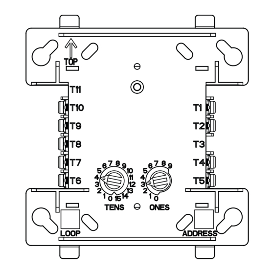
fIgure 1. controls anD InDIcators:
mountIng
The CRF-300 mounts directly to 4-inch square electrical boxes (see Figure 2A).
The box must have a minimum depth of 2
cal boxes (SMB500) are available. The module can also mount to the D355PL
or DNR(W) duct housing.
1
One FireLite Place
Northford, CT 06472
Phone: 203.484.7161
applIcatIon
Non-coded
Non-coded
Coded
Non-coded
Non-coded
Non-coded
Non-coded
Non-coded
C1071-00
1
/
inches. Surface mounted electri-
8
I56-3651-004
Advertisement

Related Manuals for Honeywell FIRE-LITE ALARMS CRF-300


Summary of Contents for Honeywell FIRE-LITE ALARMS CRF-300
- Page 1 InstallatIon anD maIntenance InstructIons crf-300 relay control module One FireLite Place Northford, CT 06472 Phone: 203.484.7161 specIfIcatIons Normal Operating Voltage: 15 to 32 VDC Maximum Current Draw: 6.5mA (LED on) Average Operating Current: 230 µA direct poll; 255 µA group poll EOL Resistance: Not used Temperature Range:...
- Page 2 fIgure 2a. moDule mountIng fIgure 2B: wIrIng wIth BarrIer: NOTE: All wiring must conform to applicable local codes, ordinances, and regulations. When using control modules in nonpower limited applications, the CB500 Module Barrier must be used to meet UL requirements for the sepa- ration of power-limited and nonpower-limited terminals and wiring.
Need help?
Do you have a question about the FIRE-LITE ALARMS CRF-300 and is the answer not in the manual?
Questions and answers