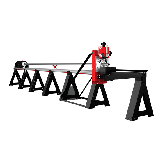
Bend-Tech DRAGON A400 Assembly Manual
Cnc plasma tube and pipe cutting machine
Hide thumbs
Also See for DRAGON A400:
- Start-up and training manual (56 pages) ,
- Maintenance & troubleshooting (56 pages) ,
- Assembly manual (44 pages)
Table of Contents
Advertisement
Quick Links
Advertisement
Table of Contents

Related Manuals for Bend-Tech DRAGON A400


Summary of Contents for Bend-Tech DRAGON A400
- Page 1 Part 1 of 1 A400 Assembly Manual Version 2.3 | English ©2020 Bend-Tech LLC...
- Page 2 We are constantly working to improve and advance our products to increase performance, user satisfaction and experience. Bend-Tech LLC assumes no responsibility for errors or omissions regarding this manual. Bend-Tech LLC assumes no liability for damages resulting from the use of the information contained in this publication.
- Page 3 Dragon A400 Assembly Manual Version 2.3 English Original Instructions March 2020 Bend-Tech, LLC 729 Prospect Ave. Osceola, WI 54020 USA (651) 257-8715 www.bend-tech.com support@bend-tech.com Bend-Tech Dragon A400 Assembly Manual...
-
Page 4: Limited Warranty
This warranty does not cover components subject to wear due to normal use of the machine such as belts, lights, tooling etc. This warranty is void if Bend-Tech, LLC has determined any failure is the result of mishandling, abuse, misuse, improper installation, improper storage, improper maintenance or unauthorized modification of the machine. -
Page 5: Customer Service
Dragon A400. Bend-Tech, LLC places great pride in customer satisfaction and it is our promise to offer you the best support available for your Dragon A400. We recognize that our support is a key factor in your success. -
Page 6: Warnings
Example ! Danger ! Exceeding the material weight limit of the Dragon A400 can result in serious injury to the operator and/or bystanders. Warning A Warning indicates there is a possibility for minor injury if the instructions are not followed correctly. - Page 7 A Note gives clarification or focuses on information that is critical or unique to an operation. Example Water Cooling system greatly reduces smoke and vapor emitted by the machine. Bend-Tech recommends use of the Water Cooling system whenever possible. Bend-Tech Dragon A400 Assembly Manual...
-
Page 8: Glossary
System for connecting multiple computers via a Local Area Network. Axis Front Gate A fixed reference line used by the Dragon A400. The Gate supports the material at the front of the machine. It consists of two Bend-Tech 7X sets of self-centering roller jaws. -
Page 9: Table Of Contents
3.1 Shipping Crate ....15 4.3 Tensioning the Drive Belt ..28 3.1.1 Dragon A400 Shop Position. . . 15 Bend-Tech Dragon A400... -
Page 10: Contents
10.2 Concrete Sleeve Anchors..51 Air Line ........39 10.3 Preparing the Floor Brackets ..52 10.4 Install Concrete Sleeve Anchors . . 53 7.1 Air Line Connection Overview ..39 Assembly Manual Bend-Tech Dragon A400... -
Page 11: Safety
Safety 1.1 Introduction Before beginning assembly of the Dragon A400, read this manual and assure that all personnel involved in assembling the machine are properly trained in lifting procedures and tool operation. Ensure all personnel are aware of the dangers and hazards involved in assembling the machine. -
Page 12: Safety Equipment
Safety Safety Precautions • Do not attempt to set up the Dragon A400 without reading this manual first. • Have the correct tools listed in the Tool List on hand. • Enlist help of 1-3 additional personnel trained to install industrial machinery. -
Page 13: Tools And Equipment
Dragon A400. Bend-Tech does not recommend attempting to assemble the machine without the tools listed in this chapter. 2.1.1 Tool List The following are the recommended tools needed to uncrate the Dragon A400 and perform the complete assembly procedure. • Forklift •... -
Page 14: Crate Parts List
Tools and Equipment 2.2 Crate Parts List Dragon A400 Assembly Miscellaneous Box • Head • Cutoff Drop Tank (1) • Tail • Swivel Levelers (14) • Rail/Rail Support Section (4-5) • Wrench (1) • Rail/Rail Support Section (3-4) • Magnetic Tool (1) •... -
Page 15: Beginning Assembly
The Dragon A400 is shipped from the Bend-Tech manufacturing facility in a custom-fabricated shipping container. This container features a steel reinforced floor and is fully-enclosed to ensure the protection of the Dragon A400 during shipping. The Dragon A400 machine is completely secured within the shipping crate for shipping purposes. Components may be bolted to the crate, shrink wrapped or secured with plastic or metal banding. -
Page 16: Getting Started
Do not remove any strapping or shrink wrap from the head of the Dragon A400. The Head will be removed last, and it is important to keep its components secure while it is being removed from the crate. -
Page 17: Rear Tail Section
The Customer should have plotted a position prior to receiving the machine. Place the Rear Tail Section with the numbered leg (5) closest to where the Head of the machine will be installed. The other end of the Rear Tail Section will not have a number. Bend-Tech Dragon A400 Assembly Manual... -
Page 18: Miscellaneous Box
• ½ in. Wrench The Dragon A400 Rail Support Legs are mounted to the floor of the shipping crate using the Floor Brackets. When assembling the machine, the Floor Brackets should be left in place. The Installer will use the Swivel Levelers to true the machine then bolt it to the floor using the Floor Brackets. -
Page 19: Rail And Rail Beam Sections
Cut the metal strapping and remove the Rail Beam sections. Locate the Rail Beam section with a “5” sticker and a “4” sticker. Locate the No. 4 Rail Support Leg and remove it from the crate. Bend-Tech Dragon A400 Assembly Manual... -
Page 20: Installing Rail Beam Sections
Set the No. 4 end of the 4/5 Rail Beam on the No. 4 Rail Support Leg. Tools Needed • Rubber mallet or plastic dead blow hammer If necessary, use a rubber mallet or a plastic dead blow hammer to tap the rails into place. Assembly Manual Bend-Tech Dragon A400... -
Page 21: Fastening The Rail Beam To The Support Leg
Head of the machine. ! Danger ! The Head of the machine is heavy. If the Head falls or tips over it could cause severe injury or death. Bend-Tech Dragon A400 Assembly Manual... -
Page 22: Placing The Head Using A Forklift
Rail to be put in place. Position Forks Here Before placing the machine ensure the Swivel Levelers are installed in each of the Rail Support Legs as outlined in Section 3.5. Assembly Manual Bend-Tech Dragon A400... -
Page 23: Complete The Rail Beam
No. 4 end of the 3/4 Rail Beam. This may require lifting the Tail and No. 4/5 Rail Beam as an assembly. Avoid sliding the assembled Rail Beam sections as this could damage the Swivel Levelers. Sliding the machine on the floor could damage the Swivel Levelers. Bend-Tech Dragon A400 Assembly Manual... -
Page 24: Secure The Rail Support Legs
With the Rails tightened to the Rail Beams, the Rail Beams can now be tightened to the Rail Support Legs. Tighten these securely by hand. 3.12 Belt Track Guide Tools Needed • 5/32 in. Allen wrench Hardware Needed • Hardware Bag No. 3 Assembly Manual Bend-Tech Dragon A400... -
Page 25: Beak
No. 5 stickers to the No. 4 and No. 5 positions on the Rail and Rail Support Legs. The Rail Beam at the Tail of the machine is pre-assembled at the Bend-Tech manufacturing facility and will arrive with the Belt Track Guide pre-installed. 3.13 Beak... -
Page 26: Installing The Beak
Support Legs and the Beak. On machines without a Powered Gate the Beak will attach to the Head using eight bolts. If the machine is equipped with a Powered Gate the Beak will attach using four bolts. Assembly Manual Bend-Tech Dragon A400... -
Page 27: Drive Belt Installation
Drive Belt Installation 4.1 Drive Belt Pre-Installation The Dragon A400 is delivered with the Drive Belt mounted on the Head of the machine. The Drive Belt is pre-installed around the Drive Belt Pulley and the idler pulleys located on the Trolley. -
Page 28: Tensioning The Drive Belt
Place a finger under the Drive Belt two feet from the end of the Drive Belt Clamp Block. Push straight down on the Belt Tension Tool with the right index finger while supporting the Drive Belt with the left hand. 1 ft. 2 ft. 1 ft. 2 ft. Belt Tension Tool Belt Assembly Manual Bend-Tech Dragon A400... -
Page 29: Tool
To lock in Drive Belt tension, thread the second ¾ in. nut onto the Drive Belt Tension adjuster. Tighten the locking nut with a ¾ in. socket and ratchet or ¾ in. wrench against the adjustment nut by turning it clockwise. Bend-Tech Dragon A400 Assembly Manual... - Page 30 Drive Belt Installation Assembly Manual Bend-Tech Dragon A400...
-
Page 31: Cables And Control Box
Cables and Control Box 5.1 Cable Pre-Installation The Dragon A400 is delivered with the Cable Track rolled up and shrink wrapped at the front of the machine, just behind the Trolley. The cables are pre-connected to the various components on the Head of the Dragon A400. -
Page 32: Installing The Cable Track
5.4 Connect to Control Box With the cables routed along the Rail Beam, insert the cables in their appropriate connections at the Control Box. Both the cables and the Control Box will be clearly labeled. Tighten securely by hand. Assembly Manual Bend-Tech Dragon A400... -
Page 33: Control Box Connections
EStop EStop C-Axis Cable Connection Lifter Air Line Connection Ethernet Cable Connection Control Box Latch Engraver Air Line Connection Air Line Connection Laser Main Power Switch Main Power Cable Engraver Torch Connection Main Power Fuses Bend-Tech Dragon A400 Assembly Manual... - Page 34 Cables and Control Box Assembly Manual Bend-Tech Dragon A400...
-
Page 35: Trolley
Locate the box containing the Trolley Cover. The Trolley Cover consists of three pieces: • Chuck Housing • Front Plate • Rear Plate The hardware to assemble and attach the Trolley Cover to the Trolley is found in Hardware Bag No. 5. Bend-Tech Dragon A400 Assembly Manual... -
Page 36: Front Plate
Chrome Plastic Collar E-Stop Switch 6.2.4 Attaching To The Trolley Place the Chuck Cover with the Front Plate mounted onto the Trolley. Secure to the Trolley using screws from Hardware Bag No. 5. Tighten securely by hand. Assembly Manual Bend-Tech Dragon A400... -
Page 37: Rear Plate
Rear Plate. Fasten the Rear Plate to the Chuck Cover using the hardware supplied in Hardware Bag No. 5. Tighten securely using a ⅛ in. Allen wrench. E-Stop Switch Chuck Key Housing Rear Plate Bend-Tech Dragon A400 Assembly Manual... - Page 38 Trolley Assembly Manual Bend-Tech Dragon A400...
-
Page 39: Air Line
Air Line 7.1 Air Line Connection Overview The Dragon A400 requires two air line feeds. One air line is connected to the air inlet on the Control Box. A second air line is connected to the Hypertherm. It is recommended that the air supply to the Dragon A400 be equipped with an air water separator and filter. - Page 40 Air Line Assembly Manual Bend-Tech Dragon A400...
-
Page 41: Torch
5.5. Connect the loose end of the Torch Cable to the power cable connection at the back of the Hypertherm unit. 8.1.1 Torch Ground Connect the alligator clamp from the Hypertherm Alligator Clamp unit to the ground cable on the Dragon A400. Bend-Tech Dragon A400 Assembly Manual... -
Page 42: Torch Lead
Toolhead. It is recommended that the Torch lead be secured so it loops up above the components at the top of the Toolhead. The Hypertherm unit requires at least 85 psi at its air connection. Consult the Hypertherm Operator Manual for complete specifications. Assembly Manual Bend-Tech Dragon A400... -
Page 43: Preparing The Torch Wand
Customer will need to remove this gear rack in order to mount the Torch on the Toolhead. On the Hypertherm Powermax45 the gear rack is secured to the wand using two Phillips head screws. Remove these screws. Remove the gear rack. The Torch is now ready to be mounted on the Toolhead. Bend-Tech Dragon A400 Assembly Manual... -
Page 44: Brass Gear Rack Hypertherm Powermax65/85
Torch rack gear, by twisting the Positioning Sleeve counterclockwise. Remove the Gear Rack. Reassemble the Torch in the order is was disassembled. The Torch is now ready to be mounted on the Toolhead. When reassembling the Torch, do not reinstall the rack gear. Assembly Manual Bend-Tech Dragon A400... -
Page 45: Install The Torch Wand
The Operator will perform the Torch Mount procedure to set Torch operating height as outlined in the Start-Up and Training Manual. With the Powermax45 unit, ensure the Torch disable switch is in the ready to fire position. Bend-Tech Dragon A400 Assembly Manual... - Page 46 Torch Assembly Manual Bend-Tech Dragon A400...
-
Page 47: Leveling And Alignment
Leveling and Alignment 9.1 Leveling and Alignment Overview Ensuring the Dragon A400 is straight and level is the most critical part of the installation of the machine. Many operational difficulties can be traced back to improper machine installation, and the majority of installation issues center around the machine not being true. -
Page 48: Checking Rail Level
Each Rail section should be checked for level side-to-side and lengthwise using a bubble level. If the Rail needs to be adjusted the Technician can use the Swivel Levelers provided with the Dragon A400. The Swivel Levelers should be installed Level upon assembly. -
Page 49: Rail Splices
Aligning the Rail Splices is one of the most difficult and time-consuming parts of the assembly process. Ensuring Rail Splices are straight and even is critical to the setup of the Dragon A400. Bend-Tech recommends experienced personnel perform the Rail Splice installation. - Page 50 Leveling and Alignment Assembly Manual Bend-Tech Dragon A400...
-
Page 51: Mounting To The Floor
Bend-Tech requires using ⅜ in. diameter, 3 in. long concrete sleeve anchors to mount the Dragon A400. Installing the concrete sleeve anchors will require a 7/16 in. concrete drill bit. One concrete sleeve anchor per Floor Bracket is sufficient for anchoring the Dragon A400. -
Page 52: Preparing The Floor Brackets
Drill the holes to the depth specified by the concrete sleeve anchor manufacturer. Once holes are drilled, clean the holes out with a vacuum or compressed air and re-install the Floor Brackets. Do not tighten the Floor Brackets onto the Rail Beam Support Legs at this time. Assembly Manual Bend-Tech Dragon A400... -
Page 53: Install Concrete Sleeve Anchors
(typically 8 lb ft. for ⅜ in. concrete sleeve anchor). Tighten the Floor Bracket to the Rail Beam Support Leg. Installing concrete sleeve anchors requires the use of a hammer drill. 7/16 in. Concrete Drill 3/8 in. Concrete Sleeve Anchor Bend-Tech Dragon A400 Assembly Manual... - Page 54 Mounting to the Floor Assembly Manual Bend-Tech Dragon A400...
- Page 55 Attention Upon completion of Dragon A400 assembly, please proceed to Start-up and Training Manual Part 1.
- Page 56 Bend-Tech, LLC 729 Prospect Ave. Osceola, WI 54020 1-651-257-8715 sales@bend-tech.com www.bend-tech.com...
Need help?
Do you have a question about the DRAGON A400 and is the answer not in the manual?
Questions and answers