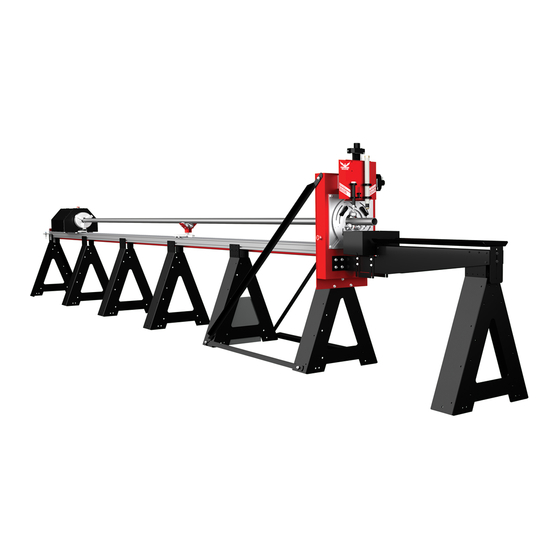
Bend-Tech Dragon A400 Start-Up And Training Manual
Hide thumbs
Also See for Dragon A400:
- Assembly manual (56 pages) ,
- Maintenance & troubleshooting (56 pages) ,
- Start-up and training manual (44 pages)

Related Manuals for Bend-Tech Dragon A400


Summary of Contents for Bend-Tech Dragon A400
- Page 1 Part 2 of 4 A400 Start-Up and Training Manual Part 2: Machine Start-Up and Walkthrough Version 2.2 | English ©2020 Bend-Tech LLC...
- Page 2 We are constantly working to improve and advance our products to improve product performance, user satisfaction and experience. Bend-Tech LLC assumes no responsibility for errors or omissions regarding this manual. Bend-Tech LLC assumes no liability for damages resulting from the use of the information contained in this publication.
- Page 3 Dragon A400 Start-Up and Training Manual Version 2.2 English Original Instructions January 2020 Bend-Tech LLC 729 Prospect Ave. Osceola, WI 54020 USA (651) 257-8715 www.bend-tech.com support@bend-tech.com Bend-Tech Dragon A400 Start-Up and Training Manual...
-
Page 4: Table Of Contents
1.6.1 C Axis Control Box ..16 2.2.2 Gate Eccentric Bearing ..26 1.6.2 Main Power Cord ... 16 Start-Up and Training Manual Bend-Tech Dragon A400... -
Page 5: Contents
3.1.1 Ethernet Connection ..41 2.4.5 Engraver Air Regulators..33 3.2 Booting Up The Dragon A400 ..42 2.4.6 Engraver Bleeder Valve ..34 3.2.1 Power On Computer . - Page 6 3.6.2 Hypertherm Cut Type ..53 3.6.3 Hypertherm Air Supply ..54 3.6.4 Hypertherm PSI Settings ..54 3.6.5 Hypertherm Cut Settings ..54 Start-Up and Training Manual Bend-Tech Dragon A400...
-
Page 7: Setup Inspection
An improperly assembled machine can create numerous problems once it comes time to power up the machine and begin operation. This chapter is set up as a procedural. Following this procedure will ensure the Dragon A400 is set up properly before it is powered up for operation. -
Page 8: Rail
The Rail is assembled in sections. The number of sections will depend on the length of the machine. There can be up to four Rail sections on the Dragon A400. It is critical that these sections are straight and level to insure proper operation of the Trolley, and proper feed of material to the Toolhead. -
Page 9: Trolley
Splice installation. 1.3 Trolley The Dragon A400 uses the Trolley to position the material during the machine’s cutting process. Ensuring the Trolley is assembled correctly, and is mounted on the Rail correctly, is critical to the operation of the machine. -
Page 10: Trolley Bearing Adjustment
Rail is level and straight but the Trolley is still binding, it will be necessary to inspect and measure the Rail to ensure it is Left Side Adjustable not out of alignment. Eccentric Bearings Start-Up and Training Bend-Tech Dragon A400... -
Page 11: Drive Belt Alignment
Drive Pulley to the X Axis motor mount surface. The distance should measure ⅜ in. or .375 in. A slight difference in measurement is acceptable but it should be close to the specified measurement. X Axis Motor Mount Surface Belt Belt Pulley Bend-Tech Dragon A400 Start-Up and Training... -
Page 12: Drive Belt Clamp
It is important to tension the Drive Belt to ensure consistent operation of the Dragon A400. Before setting Drive Belt tension ensure all steps in section 1.4 have been performed. -
Page 13: Checking Drive Belt Tension
Tension Tool clicks, observe where the top face of the lever crosses the plane on the body of the tool. This position indicates belt tension. Belt Tension 120 lbs 1 ft. 2 ft. Belt Tension Tool Improper Drive Belt tension will lead to inconsistent Trolley operation. Bend-Tech Dragon A400 Start-Up and Training... -
Page 14: Drive Belt Tension Nut
To lock in Drive Belt tension, thread the second ¾ in. nut onto the Drive Belt Tension adjuster. Holding the adjustment nut with a ¾ in. wrench, tighten the locking nut with a ¾ in. socket and ratchet or ¾ in. wrench against the adjustment nut slightly by turning it clockwise. Start-Up and Training Bend-Tech Dragon A400... -
Page 15: Control Box
Ensuring the Control Box is properly and securely mounted is critical to long-term functioning of its internal components and the Dragon A400. Ensure all cables are properly inserted and secured in their respective connectors. -
Page 16: C Axis Control Box
Setup Inspection Not all machines will use the C and Gate connections. 1.6.1 C Axis Control Box On Dragon A400 machines with a Powered C Axis Gate, the Control Box will be equipped with Control Box a C Axis Control Box piggybacked onto the Control Box. -
Page 17: Breakout Board
Board. Press on the Breakout Board firmly to ensure it is seated into each motor driver. No other inspection is necessary within the Control Box. ! Caution ! Ensure power is disconnected from the machine before opening the Control Box. Press Here when checking the Breakout Board Bend-Tech Dragon A400 Start-Up and Training... -
Page 18: Motor Cables
Failure to do this will result in improper function of the machine and could possibly damage the machine. ! Warning ! Ensure the Main Power Switch is off (O) before handling Axis Sensor Cables. Start-Up and Training Bend-Tech Dragon A400... -
Page 19: E-Stop Cables
The Ethernet Port is located near the center of the Control Box. Ensure the Ethernet cable that connects the Dragon A400 computer to the Control Box is connected and seated in the Ethernet Port cable receptacle, and that it is securely clipped in place. -
Page 20: Air Line Connection
Cord is seated in its connection. 1.6.14 Tool Connections The tool connections for the Dragon A400 are located at the bottom right of the Control Box. The Engraver uses the left hand connection, the Torch uses the center connection. The Torch cable should run to the Torch power supply. -
Page 21: Power And Control Connections
Setup Inspection 1.7 Power and Control Connections The Dragon A400 Drive Motors are connected to the Control Box using Drive Motor Cables. Homing Sensors are connected to the Control Box using Homing Sensor Cables. Air-powered components are connected to the Control Box using plastic air lines. The Torch is grounded through the Trolley via a Ground Cable. -
Page 22: Sensor Connections
Air line connections are achieved via pneufit, push-in style connectors. The plastic air lines that power various components on the Dragon A400 push into the respective pneufit connector to achieve connection. It is important to insure that all air line connections are securely seated and not leaking at each connection point for proper machine operation. -
Page 23: Ground Cable
Trolley. The nut connecting the Ground Cable should be tight, and is pre- torqued during assembly by Bend-Tech setup technicians. It is not necessary for the Technician or Operator to alter the pre-assembled Ground Cable connection. - Page 24 Setup Inspection Start-Up and Training Bend-Tech Dragon A400...
-
Page 25: Machine Walk Through
2.2 Gate The Gate is located at the front of the Dragon A400. The Gate works in conjunction with the Chuck to support and move material through its cutting process. Bend-Tech Dragon A400... -
Page 26: Gate Overview
Machine Walk Through 2.2.1 Gate Overview The Gate is important in the operation of the Dragon A400 as it combines with the Chuck to hold the material securely in place during the cutting process. The Powered Gate also plays a key role in the processing of angle material and channel material. -
Page 27: Gate Lead Screws
Gate. Gate Lead Screws should operate smoothly with minimal force applied by the Operator and with no binding throughout the travel. 2.2.4 Gate Adjustment Front Lead Screw The Dragon A400 is supplied with a ¼ in. T-handle Allen wrench. Bend-Tech Dragon A400 Start-Up and Training... -
Page 28: Gate Bearings
The adjustable Gate component bearings are set at the factory and require no further adjustment by the Operator. 2.2.6 Gate Rollers Gate Rollers should spin freely and operate smoothly with minimal play. The Gate Rollers require no adjustment by the Operator. Start-Up and Training Bend-Tech Dragon A400... -
Page 29: Gate Clamp
The Gate Clamp is critical to keeping round stock in position during the cutting operation Gate Clamp of the Dragon A400. Always lock the Gate in position with the Gate Lead Screws in the 12 o’clock and 3 o’clock positions. -
Page 30: Material Support Lift
Machine Walk Through 2.3 Material Support Lift The Material Support Lift allows the Dragon A400 to process extremely long or thin material. Long Material can sag under its own weight which can affect machine operation and accuracy. 2.3.1 Material Support Lift Overview Depending on the type and length of stock being cut, it may be necessary to utilize the Material Support Lift to prevent material from sagging. -
Page 31: Air Cylinder Adjustment
2.4 Toolhead The Toolhead is located at the front of the Dragon A400. The machine uses the Toolhead to initiate and manipulate tools through the machine’s cutting operations. 2.4.1 Toolhead Overview The Toolhead on the Dragon A400 serves as the tool mount and the vehicle for engaging the tools vertically and horizontally during the machine’s operational processes. -
Page 32: Toolhead Actuators
Vertical Actuator and horizontal movement of Screw the Toolhead. The Actuators should be kept clean and free of dust and debris. The Actuators are key to smooth, precise and consistent operation of the Toolhead. Start-Up and Training Bend-Tech Dragon A400... -
Page 33: Marker
The Engraver is driven by pressurized air. It uses two separate regulators located just behind the Toolhead. The left side regulator controls the Engraver and is pre-set at the Bend-Tech manufacturing facility to 70 PSI. The right side regulator controls the Engraver air cylinder and is pre-set at the Bend-Tech manufacturing facility to 5-10 PSI. -
Page 34: Engraver Bleeder Valve
Cylinder 2.4.8 Laser The Laser is used to calibrate the Dragon A400 tools in relation to the material. The Laser is mounted and calibrated at the Bend-Tech manufacturing facility. No adjustment of the Laser is necessary. ! Warning ! The Laser can damage human retinas. Never look directly into the Laser. -
Page 35: Emergency Stops (E-Stops)
E-Stop. 2.5.4 Homing Switches The Dragon A400 uses five Homing Sensors; six when the machine is equipped with the Powered Gate. These should be checked for function on initial startup using a metal tool such as the blade of a screwdriver. When touched with a metal tool the sensor will either light up or the sensor light will go out, depending on the location and type of the sensor. -
Page 36: Homing Sensor Designations And Locations
2.5.6 Homing Sensor Cable Connections Homing Sensor Cable Connections should be checked to ensure they are tight and secure. Homing Sensor Cable Connections are performed at the Bend-Tech manufacturing facility. Do not use tools to tighten cable connectors. Tightening cable connectors with tools can damage them and affect the performance of the machine. -
Page 37: Motor Cable Connections
Homing Sensor Cable Connections are also performed at the Bend-Tech manufacturing facility. However, it is necessary for the Customer to connect the cables for the X Axis and Y Axis motors when the Dragon A400 is initially assembled. The X Axis and Y Axis connectors are located on the Trolley. -
Page 38: Hypertherm Unit
2.7.1 Hypertherm Overview Bend-Tech recommends the Hypertherm Powermax45 XP, Powermax65 or Powermax85 for use with the Dragon A400. The Customer can purchase the Dragon A400 supplied with the desired Hypertherm machine or it can be purchased separately. 2.7.2 Hypertherm Cable The Dragon A400 is supplied with a cable that connects the Hypertherm to the machine’s... -
Page 39: Amperage
Machine Walk Through 2.7.3 Amperage Hypertherm units are available for use with the Dragon A400 in 45, 65 and 85 amp versions. The amperage the Customer chooses will depend on the thickness of material being cut as well as the amount of usage the Dragon A400 will see. -
Page 40: Consumables
2.7.6 Consumables It is recommended that the Customer have additional consumables on hand when operating the Dragon A400. Worn consumables can result in wider cuts and less precise cuts. Consumables are available through Hypertherm website or via a Hypertherm distributor. -
Page 41: Machine Control Startup
Software, as well as Newfangled Solutions Mach3 six-axis CNC controller software package. Mach3 is the machine driving software for the Dragon A400. Bend-Tech software uses Mach3 to communicate with the Control Box on the Dragon A400 to control all the operations of the machine. -
Page 42: Booting Up The Dragon A400
Booting up the Dragon A400 requires following a specific procedure. Following this procedure in the proper order will ensure the Dragon A400 is up and running as quickly as possible. Failure to follow the procedure in the proper order can affect machine operation and lead to unnecessary down time. -
Page 43: Power On Computer
Chapter 1. The Operator should have thoroughly inspected all electrical connections, components and operation according to procedure in Chapter 2. Following these procedures ensures the Dragon A400 electrical control system is set up and properly and ready for operation. -
Page 44: Main Power Switch
In this case check all E-Stop buttons. 3.3.3 Launch Bend-Tech 7X On the home screen, click Bend-Tech 7X icon to launch the software program. An interface will open showing options to launch Dragon CAD, Dragon CAM and Dragon CAD + Dragon CAM. -
Page 45: Dragon Cam
Machine Control Startup 3.3.5 Dragon CAM With the Bend Tech 7X program open, click on Dragon CAM to begin operation of the Dragon A400. 3.3.6 Machine Library Open Machine Library. Bend-Tech Dragon A400 Start-Up and Training... - Page 46 Once the machine is named, it can be found in the Machine Library upon boot up. Click Close. Each Dragon leaves the Bend-Tech facility pre-programmed with the name “Dragon.” The Operator can continue to use this name if desired. The factory calibrated machine should be saved and remain unaltered as a baseline for the Dragon A400.
-
Page 47: Machine Control
In some cases, if there is only one machine entered in the Machine Library, the program may go straight to Mach3 and not present a Machine Selection window after clicking Machine Control. If Mach3 does not connect properly repeat Power On Dragon A400 Control Box procedure beginning at Section 3.3. 3.3.8 Mach3 Machine Control Mach3 CNC software control interface will appear. -
Page 48: Enable Machine
At the bottom center of the Machine Control screen, click Jog Controls to open the Jog Controls interface screen. Jog controls are referenced to their respective motor (see Motor Location and Operation Index table 3.4.2). Start-Up and Training Bend-Tech Dragon A400... -
Page 49: Index
Material Support Lifter Down 3.4.3 Jogging the Machine With the Jog Controls screen open the Operator can jog the Dragon A400 to observe that all controls are in working order. ! Caution ! Avoid jogging the machine to the limits of its operation. -
Page 50: Homing The Machine
Machine Control Startup 3.5 Homing The Machine Before beginning operations with the Dragon A400, the machine must determine Home for all of its operating Axes. This allows the machine to operate efficiently and within its operational parameters. 3.5.1 Homing An AXIS The AXIS feature on the Machine Controls screen allows the operator to Home each Axis of the Dragon A400. -
Page 51: Jog The Trolley
Trolley contacts the end of the Rail the Operator will see a Machine Disabled signal. This is a safety feature designed to protect the Dragon A400 from being damaged. The Operator will need to click Enable Machine to resume machine operation. -
Page 52: Home All Axis
Ensure the Hypertherm unit is set to cut the type of material or to perform the cutting procedure as intended. The Hypertherm will go to default PSI settings. However, the Operator will need to adjust amperage as necessary. Start-Up and Training Bend-Tech Dragon A400... -
Page 53: Hypertherm Power Switch
Powermax65 and Powermax85 is located on the back of the machine. Turn it clockwise to power on the unit. ! Caution ! Ensure the Hypertherm ground clamp is connected to the Dragon A400 ground wire. Ensure the air supply is connected to the Hypertherm. -
Page 54: Hypertherm Air Supply
The Customer should ensure the air supply for the Dragon A400 is appropriate to operate the Hypertherm as well as other working aspects of the machine. If connected to a separate air source the Customer should ensure the air source is appropriate to supply the Hypertherm unit. - Page 55 Attention Upon completion of Start-up and Training Manual Part 2, please proceed to Start-up and Training Manual Part 3.
- Page 56 Bend-Tech, LLC 729 Prospect Ave. Osceola, WI 54020 1-651-257-8715 sales@bend-tech.com www.bend-tech.com...
Need help?
Do you have a question about the Dragon A400 and is the answer not in the manual?
Questions and answers
where is the key code/serial code on the dragon machine