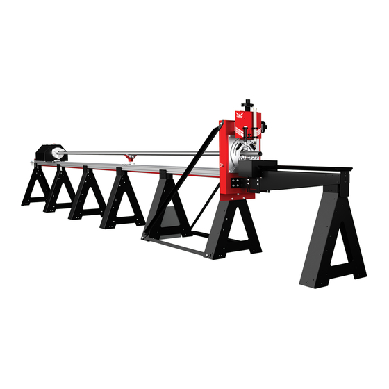
Bend-Tech DRAGON A400 Assembly Manual
Hide thumbs
Also See for DRAGON A400:
- Start-up and training manual (56 pages) ,
- Assembly manual (56 pages) ,
- Maintenance & troubleshooting (56 pages)
Table of Contents
Advertisement
Quick Links
Advertisement
Table of Contents

Related Manuals for Bend-Tech DRAGON A400


Summary of Contents for Bend-Tech DRAGON A400
- Page 1 Part 1 of 1 A400 Assembly Manual Revision 5 | English ©2020 Bend-Tech LLC...
- Page 2 We are constantly working to improve and advance our products to increase performance, user satisfaction and experience. Bend-Tech LLC assumes no responsibility for errors or omissions regarding this manual. Bend-Tech LLC assumes no liability for damages resulting from the use of the information contained in this publication.
- Page 3 Dragon A400 Assembly Manual Revision 5 English Original Instructions December 2020 Bend-Tech, LLC 729 Prospect Ave. Osceola, WI 54020 USA (651) 257-8715 www.bend-tech.com support@bend-tech.com Bend-Tech Dragon A400 Assembly Manual...
- Page 4 This warranty does not cover components subject to wear due to normal use of the machine such as belts, lights, tooling etc. This warranty is void if Bend-Tech, LLC has determined any failure is the result of mishandling, abuse, misuse, improper installation, improper storage, improper maintenance or unauthorized modification of the machine.
-
Page 5: Customer Service
Contact Us Bend-Tech’s hours of operation are Monday - Friday, 8:00 - 5:00 EST. The Bend-Tech support team and sales team are always available during our hours of operation. Phone: 651-257-8715 Email: Sales team: sales@bend-tech.com... -
Page 6: Warnings
Example ! Danger ! Exceeding the material weight limit of the Dragon A400 can result in serious injury to the operator and/or bystanders. Warning A Warning indicates there is a possibility for minor injury if the instructions are not followed correctly. - Page 7 A Note gives clarification or focuses on information that is critical or unique to an operation. Example The material coolant system greatly reduces smoke and vapor emitted by the machine. Bend-Tech recommends using the material coolant system with aluminum and stainless steel material. Bend-Tech Dragon A400...
-
Page 8: Glossary
Glossary Glossary Axis Interface A fixed reference line used by the Dragon A400. Any particular screen display generated by Bend-Tech software. Bend-Tech 7x Mach3 Machine design software - CAD. Machine driver software. Parts Catcher Breakout Board. The parts catcher is placed at the front of Material Support Lift the machine to catch parts as they are cut. -
Page 9: Table Of Contents
3.1 Shipping Crate ....15 3.1.1 Dragon A400 Shop Position. . . 15 3.2 Crate Disassembly ....15... -
Page 10: Contents
10.1.2 Torch Lead ....38 4.2 Straightening the Dragon A400 ..26 10.2 Install the Torch Wand ..39 4.2.1 Checking the Straightness . -
Page 11: Safety
Safety 1.1 Introduction Before assembling the Dragon A400, read this manual and ensure that all personnel involved in assembling the machine are properly trained in lifting procedures and tool operation. Ensure all personnel are aware of the dangers and hazards involved in assembling the machine. -
Page 12: Safety Equipment
1.2.1 Safety Equipment Bend-Tech recommends using the proper safety equipment when installing the Dragon A400. Safety equipment standards for each shop should be outlined in Occupational Safety and Health Administration (OSHA) standards. Also, individual shops may have their own standards. -
Page 13: Tools And Equipment
Dragon A400. Bend-Tech does not recommend attempting to assemble the machine without the tools listed in this chapter. 2.1.1 Tool List The following are the recommended tools needed to uncrate the Dragon A400 and perform the complete assembly procedure. • Forklift •... -
Page 14: Crate Parts List
Tools and Equipment 2.2 Crate Parts List Dragon A400 Assembly Miscellaneous Box • Machine Head • Training Packet (1) • Machine Tail • Plasma Cutting Guide (1) • Rail & Beam Section (2) • Cutoff Drop Tank (1) • Rail Support Leg (2) •... -
Page 15: Assembling The Dragon
This crate features a steel reinforced floor and is fully-enclosed to ensure the protection of the Dragon A400 during shipping. The Dragon A400 machine is completely secured within the crate for shipping purposes. Components may be bolted to the crate, shrink wrapped or secured with plastic or metal banding. -
Page 16: Getting Started
Do not remove any strapping or shrink wrap from the head of the Dragon A400. It is important to keep components secure while the Head is being removed from the crate. -
Page 17: Miscellaneous Box
Cap Screws. These will be needed to assemble the Rail and Rail Beam, and the Head of the machine. The Dragon A400 Rail Support Legs are mounted to the floor of the shipping crate using the Floor Brackets. When assembling the machine, the Floor Brackets should be left in place. -
Page 18: Unpacking The Crate
Remove all other contents of the crate before attempting to move the head of the machine. ! Danger ! The Head of the machine is heavy. If the Head falls or tips over it could cause severe injury or death. Bend-Tech Dragon A400 Assembly Manual... -
Page 19: Installing The Beams
The Dragon A400 requires a minimum of 32 feet of space. Position Forks Here Important Due to its size and weight, Bend-Tech does not recommend placing the head of the machine manually. Before placing the machine, ensure... -
Page 20: Slide Support Leg #4 Into Position
4. If necessary, use a rubber mallet or dead blow plastic hammer to seat the beam sections together. The end labeled 5 will need to be supported until the tail of the machine is installed. Bend-Tech Dragon A400 Assembly Manual... -
Page 21: Fasten The Support Legs To The Beams
The fifth rack is installed to the tail of the machine. When the tail of the machine is installed, the fifth rack will need to be adjusted along with the rest using the bridge rack spacer to set the spacing between racks. This will ensure the racks are spaced correctly. Bend-Tech Dragon A400 Assembly Manual... -
Page 22: Placing The Tail
Bag No. 3. They only need to be secured at the rail joints. There are four screws needed for each joint. Once the rail sections are secured, tighten all the fasteners on the support legs. Secure the rail splices to the beams Bend-Tech Dragon A400 Assembly Manual... -
Page 23: Installing The Racks
One cable track tray has a hole with a grommet, this tray shold be positioned so the hole is towards the tail of the machine. The tail of the machine and head of the machine are pre-assembled at the Bend-Tech manufacturing facility and will arrive with the cable track tray pre-installed. -
Page 24: Installing The Beak
Important Shorter machines will have a different configuration of beams and racks. Use the numbers on the beams, racks, and other components to assemble the machine in the correct order. Bend-Tech Dragon A400 Assembly Manual... -
Page 25: Leveling And Alignment
Leveling and Alignment 4.1 Leveling and Alignment Overview Ensuring the Dragon A400 is straight and level is the most critical part of the installation of the machine. Many operational difficulties can be traced back to improper machine installation, and the majority of installation issues center around the machine not being true. -
Page 26: Checking Rail Level
4.2 Straightening the Dragon A400 Ensuring the Dragon A400 is straight is one of the most important steps in preparing the machine for operation. Bend-Tech has found the simplest and best way to determine if the machine is straight is to use a length of string. -
Page 27: Checking The Straightness
Aligning the Rail Splices is one of the most difficult and time-consuming parts of the assembly process. Ensuring Rail Splices are straight and even is critical to the setup of the Dragon A400. Bend-Tech recommends experienced personnel perform the Rail Splice installation. - Page 28 Leveling and Alignment Bend-Tech Dragon A400 Assembly Manual...
-
Page 29: Mounting To The Floor
Bend-Tech requires using ⅜ in. diameter, 3 in. long concrete sleeve anchors to mount the Dragon A400. Installing the concrete sleeve anchors will require a 7/16 in. concrete drill bit. One concrete sleeve anchor per Floor Bracket is sufficient for anchoring the Dragon A400. -
Page 30: Preparing The Floor Brackets
Using a ½ in. socket and torque wrench, torque to manufacturer specs (typically 8 lb ft. for ⅜ in. concrete sleeve anchor). Tighten the Floor Bracket to the Rail Beam Support Leg. 7/16 in. Concrete Drill 3/8 in. Concrete Sleeve Anchor Bend-Tech Dragon A400 Assembly Manual... -
Page 31: Cables And Control Box
Cables and Control Box 6.1 Cable Pre-Installation The Dragon A400 is delivered with the Cable Track rolled up and shrink wrapped at the front of the machine, just behind the Trolley. The cables are pre-connected to the various components on the Head of the Dragon A400. -
Page 32: Routing Cables
6.5 Connect to Control Box With the cables routed along the Rail Beam, insert the cables in their appropriate connections at the Control Box. Both the cables and the Control Box will be clearly labeled. Tighten securely by hand. Bend-Tech Dragon A400 Assembly Manual... -
Page 33: Control Box Connections
EStop EStop C-Axis Cable Connection Lifter Air Line Connection Ethernet Cable Connection Control Box Latch Engraver Air Line Connection Air Line Connection Laser Main Power Switch Main Power Cable Engraver Torch Connection Main Power Fuses Bend-Tech Dragon A400 Assembly Manual... - Page 34 Cables and Control Box Bend-Tech Dragon A400 Assembly Manual...
-
Page 35: Air Line
Air Line 9.1 Air Line Connection Overview The Dragon A400 requires two air line feeds. One air line is connected to the air inlet on the Control Box. A second air line is connected to the Hypertherm. It is recommended that the air supply to the Dragon A400 be equipped with an air water separator and filter. - Page 36 Air Line Bend-Tech Dragon A400 Assembly Manual...
-
Page 37: Torch
Ground Cable to the power cable connection at the back of the Hypertherm unit. 10.1.1 Torch Ground Connect the alligator clamp from the Hypertherm unit to the ground cable on the Dragon A400. Alligator Clamp Bend-Tech Dragon A400 Assembly Manual... -
Page 38: Torch Lead
The Customer should ensure the Torch lead is secured so it is clear of the cables at the top of the Toolhead. It is recommended that the Torch lead be secured so it loops up above the components at the top of the Toolhead. Bend-Tech Dragon A400 Assembly Manual... -
Page 39: Install The Torch Wand
Running the Torch Mount utility is required before the Dragon Machine is ready for operation. This utility is used to set the torch operating height. The Torch Mount procedure is outlined in the Startup and Training Manual Part 3. Bend-Tech Dragon A400 Assembly Manual... - Page 40 Torch Bend-Tech Dragon A400 Assembly Manual...
- Page 41 Torch Bend-Tech Dragon A400 Assembly Manual...
- Page 42 Torch Bend-Tech Dragon A400 Assembly Manual...
- Page 43 Attention After completing the Dragon A400 assembly, please proceed to Startup and Training Manual Part 1.
- Page 44 Bend-Tech, LLC 729 Prospect Ave. Osceola, WI 54020 1-651-257-8715 sales@bend-tech.com www.bend-tech.com...
Need help?
Do you have a question about the DRAGON A400 and is the answer not in the manual?
Questions and answers