Table of Contents
Advertisement
Quick Links
TM
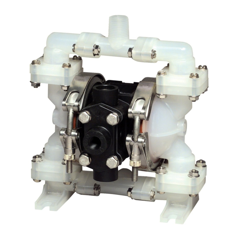
DESCRIPTION
The Model 8301 Air-Powered Diaphragm Pump is
used to transfer corrosive chemicals. The wetted
parts are polypropylene and the diaphragms are
Santoprene to resist damage from caustics, plating
liquids, brine water and other corrosive chemicals. A
silencer enclosed in the body reduces the noise. The
pump delivers a maximum capacity of fourteen
gallons per minute.
The pump has the following outstanding features:
1. Leak-Free Flange Connections
2. Side-Outlet Port Design
3. Non-Leak Manifold
4. Corrosion-Resistant Air Motor
5. Abrasion-Resistant Housing
6. Air-Valve Reset Button
7. Air Valve Requires No Lubrication
SPECIFICATIONS
Pump Ratio: .......................................................... 1:1
Air Connections:
Inlet: .................................................... 1/4" NPT (f)
Outlet: ................................................. 3/8" NPT (f)
Material Connections:
Inlet: .................................................... 1/2" NPT (f)
Outlet: ................................................. 1/2" NPT (f)
Discharge Volume per Cycle ..................... 0.025 Gal.
Maximum Size Solid: .......................................... 1/32"
Air-Supply Pressure: ................................ 20-100 PSI
Temperature Range: ................................. 32-140° F.
Net Weight: .................................................... 7.7 lbs.
670557
SERVICE INSTRUCTIONS
Diaphragm Pump
Alemite Corporation
www.alemite.com
167 Roweland Drive, Johnson City, Tennessee 37601
Figure 1: Model 8301 Diaphragm Pump
GENERAL SAFETY REQUIREMENTS
IMPORTANT: Read all instruction sheets and any
other explanatory information before beginning any
installation, operation or maintenance.
1. Check all hoses and lines for weak or damaged
condition and make sure that all connections are
secure.
NOTE: Worn or damaged parts threaten person and
property. Replace all such parts.
2. Do not use pump with any liquids not compatible
with the materials of the pump components.
3. Never exceed the maximum pressure rating of any
component in the system.
8301
SER 8301 (6-03)
Advertisement
Table of Contents

Subscribe to Our Youtube Channel
Related Manuals for Alemite 8301


Summary of Contents for Alemite 8301
- Page 1 SERVICE INSTRUCTIONS 8301 Diaphragm Pump DESCRIPTION The Model 8301 Air-Powered Diaphragm Pump is used to transfer corrosive chemicals. The wetted parts are polypropylene and the diaphragms are Santoprene to resist damage from caustics, plating liquids, brine water and other corrosive chemicals. A silencer enclosed in the body reduces the noise.
-
Page 2: Installation
7-5/16 air filter/moisture separator (such as the Alemite 5604-2) and an air-pressure regulator (such as the Alemite 7604-B) be used in the air line. 4-29/32 WARNING: The pump must be grounded to prevent any sparks when pumping flammable or volatile liquids. -
Page 3: Maintenance
SER 8301 NOTE: Use a flexible hose between the pump and 3. To obtain the maximum discharge rate, start the any piping to eliminate any vibration in the piping. pump by opening the ball valve gradually while watching the discharging fluid until the flow rate 3. -
Page 4: Outlet Check Valves
SER 8301 Reassembly: 8. Clean and inspect all parts. Replace any parts that are worn or show any signs of disintegration due to NOTE: The reassembly procedure is written for one the corrosive effects of some of the fluids. inlet valve but is identical for the other. - Page 5 SER 8301 NOTE: When the valve cage is properly seated, it will 13. Remove the “O” ring (6) from inside the center be about flush with the top of the outlet cavity. hole in body B. 5. Replace the top “O” ring (16) in the outlet cavity.
- Page 6 SER 8301 6. Push bushing and spacer into the center hole in 13. Place the diaphragm cushion (18) on the center body A. Press it firmly enough to seat ther “O” rings. rod (24) next to body B (27). 7. Insert the center rod (24) through the spacer (9) 14.
- Page 7 SER 8301 NOTE: The two end castings each have an arrow on 7. Remove the six “O” rings from the sleeve. them. Make sure that the arrow points toward the fluid outlet. The arrows will point up when the pump is 8.
- Page 8 SER 8301 page 8 page revised 6-03...
- Page 9 SER 8301 CORRECTIVE ACTION SYMPTOM POSSIBLE CAUSE(S) 1. Check air supply. Little or no flow 1. Insufficient air supply. 2. Open valve or remove 2. Closed valve or clogged line. restriction. 3. Increase piping size; should 3. Piping too small.
- Page 10 SER 8301 Minor Repair Kits 393630-75 Check Valves and Diaphragm Kit Item No. Part No. Description Qty. 5 .... 393630-5 ....“O” Ring ................2 14 ..393630-14 .... Check Valve Disk ..............4 16 ..393630-16 .... “O” Ring ................8 46 ..
- Page 11 SER 8301 PARTS LIST – Model 8301 Diaphragm Pump (Figure 6) Item No. Part No. Description Qty. 11 ....393630-1 ..Tie Rod (Stainless Steel) ............6 12 ....393630-2 ..Washer (Stainless Steel) ............24 13 ....393630-3 ..Spring Washer (Stainless Steel) ..........24 14 ....
Need help?
Do you have a question about the 8301 and is the answer not in the manual?
Questions and answers