Advertisement
Available languages
Available languages
Quick Links
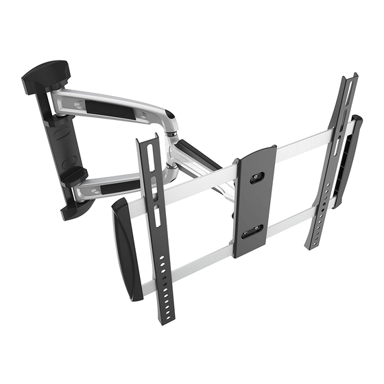
Wandhalterung für TV / Monitor
S0644
200x200
300x200
300x300
400x300
400x400
MONTAGEANLEITUNG
ACHTUNG: NIEMALS DAS MAXIMAL
ZULÄSSIGE BELASTUNGSGEWICHT
ÜBERSCHREITEN. MISSACHTUNG
KANN ZU SACHSCHÄDEN ODER
SCHWEREN VERLETZUNGEN FÜHREN!
35kg
(77lbs)
MAX
v.17.01
Advertisement

Subscribe to Our Youtube Channel
Related Manuals for ricoo S0644


Summary of Contents for ricoo S0644
- Page 1 Wandhalterung für TV / Monitor MONTAGEANLEITUNG v.17.01 ACHTUNG: NIEMALS DAS MAXIMAL ZULÄSSIGE BELASTUNGSGEWICHT ÜBERSCHREITEN. MISSACHTUNG KANN ZU SACHSCHÄDEN ODER SCHWEREN VERLETZUNGEN FÜHREN! 35kg 200x200 S0644 300x200 (77lbs) 300x300 400x300 400x400...
- Page 2 ACHTUNG: Lesen Sie die gesamte Bedienungsanleitung durch, bevor Sie mit der Montage beginnen. WARNUNG • Beginnen Sie nicht mit der Montage, bis Sie alle Anweisungen und Warnungen, welche in dieser Montageanleitung vorhanden sind, durchgelesen und verstanden haben. Wenn Sie Fragen zu den Anweisungen oder Warnungen haben, kontaktieren Sie bitte Ihren Händler.
- Page 3 Lieferumfang WICHTIG: Stellen Sie vor der Montage sicher, dass alle Teile welche hier aufgeführt sind, bei der Lieferung dabei sind. Sollten Teile fehlen oder defekt sein, kontaktieren Sie Ihren Händler. Grundgerüst (x1) Schablone (x1) 3mm Inbusschlüssel (x1) 5mm Inbusschlüssel (x1) Schraubenschlüssel (x1) Paket M M8x30 (x4)
- Page 4 1. Demontage der Frontplatte Lösen Sie drei Schraubenmuttern an der Frontplattenaufnahme. Bitte achten Sie darauf, dass sechs schwarze Plastikscheiben nich abhanden kommen, da diese für den weiteren Zusammenbau benötigt werden. Insgesamt sollen es 3 Stk. Schraubenmuttern und 6 Stk. Plastikscheiben sein. English Deutsch...
- Page 5 2. Demontage der Plastikabdeckungen 3. Überprüfung der Lochabstände Bitte überprüfen Sie VOR der Montage den Lochabstand zwischen den Befestigungs-lö- chern an Ihrem Bildschirm! VESA-Befestigungslöcher Vertikal / Senkrecht Horizontal / Waagerecht Bildschirm Rückseite Diese Wandhalterung unterstützt folgende Lochabstände: min. 200mm - max. 400mm Horizontal / Wageerecht Vertikal / Senkrecht min.
- Page 6 4a. Befestigung an der Holzbalkenwand Holzbalken mit Balkenfinder Montagelöcher finden und die Montagelöcher bohren. markieren. Wandplatte an die Wand anschrauben. Mit dem Pfeil nach oben. Beachten: keine Unterlegscheibe für diese Schraube erforderlich. WARNUNG • Stellen Sie sicher, dass die Befestigungsschrauben in der Mitte der Balken verankert sind. Die Verwendung eines Balkenfinders wird dringend empfohlen.
- Page 7 4b. Befestigung an der Massivbetonwand Achtung: Mitgelieferte Dübel sind nur für Massivbetonwände geeignet! Montagelöcher markieren. Montagelöcher bohren. Wandplatte an die Wand anschrauben. Mit dem Pfeil nach oben. Beachten: keine Unterlegscheibe für diese Schraube erforderlich. WARNUNG Installateure müssen sicher stellen, dass die Anbaufläche das Gesamtgewicht von diesem Produkt inkl. aller angeschlossener Komponente sicher tragen kann.
- Page 8 5. Montage der dekorativen Abdeckungen Montieren Sie die dekorativen Abdeckungen entlang der Wandplatte. Achten Sie darauf, dass diese auf der Wandplatte einrasten. English Deutsch...
- Page 9 6. Anbringung der Frontplatte an den Bildschirm Oberseite des TVs Passen Sie die Montageschienen an die Montagelöcher an. Ziehen Sie anschließend die Schrauben an den Montage- schienen mit Hilfe des Inbusschlüssels an. 6-1 Für Bildschirme mit flacher Rückseite English Deutsch...
- Page 10 6-2 Für TV/Monitore mit gewölbter Rückseite oder für den freien Zugang zu den Anschlüssen Beachten: Wählen Sie die zu Ihrem TV passenden Schrauben, Unterlegscheiben und falls erforderlich die Abstandshalter. · Montieren Sie die Montageschienen so nah wie möglich zur Mitte des TV-Gerätes. ·...
- Page 11 8. Aufhängung des Bildschirms an die Wandhalterung / das Grundgerüst Den Bildschirm samt Frontplatte von oben einführen. Die obere Schraube an der Frontplatte in die vorgesehene Aussparung an der Frontplattenaufnahme einführen. Beachten: Die Frontplattenaufnahme muss sich zwischen den beiden Plastik- scheiben befinden (wie es vor dem Ausbau der Frontplatte im Schritt “1”...
- Page 12 9. Kabelführung • Schließen Sie die Kabel an Ihrem Fernseher an und führen Sie die Kabel durch die Kabelführung. ACHTUNG: • Auf genügend Kabellockerung achten, damit das Schwenken der Halterung nicht beinträchtigt wird. • Kabel möglichst getrennt durchführen (obere oder untere Abdeckung) um Signalstörung zu vermeiden. English Deutsch...
- Page 13 10. Geradestellung der Frontplatte Diese Wandhalterung besitzt eine Drehfunktion der Frontplatte. Somit ist der Bildschirm in Horizontaler / Waagerechten um +/-2,5° drehbar. Dies hat den Vorteil, dass Sie den Bildschirm jederzeit horizontal ausrichten können. Um dies zu ermöglichen müssen die zwei Einstellschrauben an der Frontplatte mittelfest angezogen werden (Schritt 4). Dadurch wird es möglich sein den Bildschirm jederzeit mit den Händen ohne die Schrauben lockern zu müssen und ohne großen Kraftauf- wand waagerecht gerade stellen können, was das Ausrichten ohne Extra-Werkzeug ermöglicht.
- Page 14 12. Einstellungen / Ausrichtung Die TV-Halterung kann um 180° geschwenkt, um +5° / -12° geneigt oder um +/-2,5° gedreht werden. Wartung • Prüfen Sie in regelmäßigen Abständen (mindestens alle drei Monate), ob alle Schrauben an dem Produkt fest angezogen sind. •...
- Page 15 Full Motion LED, LCD TV Wall Mount INSTALLATION MANUAL v.17.01 CAUTION: DO NOT EXCEED RATED LISTED WEIGHT. SERIOUS INJURY OR PROPERTY DAMAGE MAY OCCUR! 35kg 200x200 S0644 300x200 (77lbs) 300x300 400x300 400x400...
- Page 16 NOTE: Read the entire instruction manual before you start installation and assembly. WARNING • Do not begin the installation until you have read and understood all the instructions and warnings contained in this installation sheet. If you have any questions regarding any of the instructions or warnings, please contact your local distributor.
- Page 17 Template (x1) Wall mount (x1) Wrench (x1) 3mm allen key (x1) 5mm allen key (x1) M5x14 (x4) M6x14 (x4) M8x20 (x4) M6x30 (x4) M8x30 (x4) M8x50 (x4) washer (x4) small spacer (x8) big spacer (x8) (x3) Concrete anchor (x4) D6 washer (x3) (x1) Deutsch English...
- Page 18 1. Disassembly the front panel. Unscrew the three nuts on the front panel holder. Please make sure that six black plastic washers don’t disappear because they are needed for further assembly. Overall, there should be 3 pcs. screw-nuts and 6 pcs. plastic washers. Deutsch English...
- Page 19 2. Disassembly of plastic covers 3. Measure distance between mounting holes Please check BEFORE installation distance between mounting holes on your display! VESA-Mounting holes Vertical / Perpendicularly Horizintally Display back This wall mount supports the following distance between holes: min. 200mm - max. 400mm Horizontally min.
- Page 20 4a. For wood stud wall mounting Find and mark the exact Drill pilot holes. location of mounting holes. Screw the wall mount onto the wall. With the arrow pointing up. Note: No washer required for this screw. WARNING • Make sure that mounting screws are anchored into the center of the studs. The use of a stud finder is highly recomended. •...
- Page 21 4b. For solid brick and concrete wall mounting Warning: Supplied plastic anchors are only suitable for solid concrete walls! Find and mark the exact location of mounting holes. Drill pilot holes. Screw the wall mount onto the wall. With the arrow pointing up. Note: No washer required for this screw.
- Page 22 5. Installing the decorative covers Install the decorative cobvers along the wall plate rail until they fit snuggly onto the wall plate. Deutsch English...
- Page 23 6. Installing the universal plate onto display Top of display Adjust the brackets to fit the mounting holes on the back side of the display and tighten all screws on the universal plaety using an allen key. 6-1 For flat back screen Deutsch English...
- Page 24 6-2 For recessed back screens or to acces A/V inputs 7. Preparation of the front plate Mount two plastic washers and a screw nut, which were removed in step 1, on the top screw of the front panel, but do not tighten. Between the two plastic washers should remain about 5mm distance. And the two bottom screws provided with each a plastic washer (from step 1).
- Page 25 8. Hooking the display onto wall mount Insert the display along with front panel from above. Insert the top screw on the front panel into the recess provided on the wall mount. Note: The front panel holder must be located between the two plastic washers (as it was before removing the front panel in step "1")! Next put on the two bottom screws each a plastic washer and a nut.
-
Page 26: Cable Management
9. Cable management • Connect the cable to your display and run the cables through the cable guide. ATTENTION: • Leave slack in the cable for arm movement. • Route the power and signal cable in different cable covers to avoid signal disturbance. Deutsch English... - Page 27 10. Positioning the front panel. This Wall Bracket has a rotation function of front plate. Therefore the screen is turnable ±2,5° horizontally. This is an advantage for the adjustment of the screen in the horizontal position at all time. To permit this, you have to screw the setting screws at medium strength (Step 4). Thereby it will be possible to adjust the screen in the horizontal position without unscrewing the screw or a big effort at all time, which is possible without extra-tools.
- Page 28 12. Adjustment The wall mount can be swivelled 180°, tilted +5°/-12° and rotated +/-2,5°. Maintenance • Check that the bracket is secure and safe to use at regular intervals (at least every three months). • Please contact your distributor if you have any questions. Done Deutsch English...
Need help?
Do you have a question about the S0644 and is the answer not in the manual?
Questions and answers