Advertisement
Available languages
Available languages
Quick Links
S2722
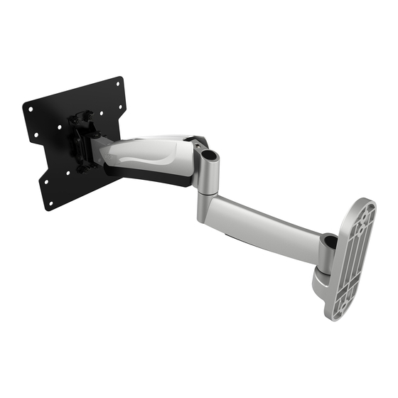
Höhenverstellbare Wandhalterung
für TV / Monitor
100x100
200x100
200x200
ACHTUNG: NIEMALS DAS MAXIMAL
ZULÄSSIGE BELASTUNGSGEWICHT
ÜBERSCHREITEN. MISSACHTUNG
KANN ZU SACHSCHÄDEN ODER
SCHWEREN VERLETZUNGEN FÜHREN!
min. 2.5 Kg (5.5 lbs)
max. 20 Kg (44 lbs)
MONTAGEANLEITUNG
BEACHTEN
Bildschirm Mindestgewicht
2,5 Kg
Deutsch
English
v.17.03
Advertisement

Related Manuals for ricoo S2722


Summary of Contents for ricoo S2722
- Page 1 TV / Monitor MONTAGEANLEITUNG v.17.03 BEACHTEN Bildschirm Mindestgewicht 2,5 Kg ACHTUNG: NIEMALS DAS MAXIMAL ZULÄSSIGE BELASTUNGSGEWICHT ÜBERSCHREITEN. MISSACHTUNG KANN ZU SACHSCHÄDEN ODER SCHWEREN VERLETZUNGEN FÜHREN! min. 2.5 Kg (5.5 lbs) S2722 100x100 200x100 max. 20 Kg (44 lbs) 200x200 Deutsch English...
- Page 2 ACHTUNG: Lesen Sie die gesamte Bedienungsanleitung durch, bevor Sie mit der Montage beginnen. WARNUNG • Beginnen Sie nicht mit der Montage, bis Sie alle Anweisungen und Warnungen, welche in dieser Montageanleitung vorhanden sind, durchgelesen und verstanden haben. Wenn Sie Fragen zu den Anweisungen oder Warnungen haben, kontaktieren Sie bitte Ihren Händler.
- Page 3 Lieferumfang WICHTIG: Stellen Sie vor der Montage sicher, dass alle Teile welche hier aufgeführt sind, bei der Lieferung dabei sind. Sollten Teile fehlen oder defekt sein, kontaktieren Sie Ihren Händler. 4mm Inbusschlüssel (x1) 6mm Inbusschlüssel (x1) Grundgerüst Schraubenschlüssel (x1) Frontplatte Paket M M8x20 (x4) M4x14 (x4)
- Page 4 Schritt 1 Bitte überprüfen Sie VOR der Montage den Lochabstand zwischen den VESA Befestigungslchern an Ihrem Bildschirm! VESA Befestigungslöcher Vertikal / Senkrecht Horizontal / Waagerecht Bildschirm Rückseite Diese Wandhalterung unterstützt folgende Lochabstände: 100mm , 200mm Horizontal / Waagerecht Vertikal / Senkrecht 100mm , 200mm Schritt 2 Deutsch...
- Page 5 Schritt 3a. Befestigung an der Holzbalkenwand 55mm (2. 2 ") ø 4.5mm (ø 3/16") Holzbalken mit Balkenfinder finden und die Montagelöcher markieren. Montagelöcher bohren. √ Wandplatte an die Wand anschrauben. WARNUNG • Stellen Sie sicher, dass die Befestigungsschrauben in der Mitte der Balken verankert sind. Die Verwendung eines Balkenfinders wird dringend empfohlen.
- Page 6 Schritt 3b. Befestigung an der Massivbetonwand 60mm (2.4") ø 10mm (ø 3/8") Montagelöcher markieren. Montagelöcher bohren. Achtung: Mitgelieferte Dübel sind nur für Massivbetonwände geeignet! √ Wandplatte an die Wand anschrauben. WARNUNG Installateure müssen sicher stellen, dass die Anbaufläche das Gesamtgewicht von diesem Produkt inkl. aller angeschlossener Komponente sicher tragen kann.
- Page 7 Schritt 4 Schritt 5 Oberseite des TVs Deutsch English...
- Page 8 M-A/M-B M-C/M-D oder · Wählen Sie die zu Ihrem TV passenden Schrauben. · Montieren Sie die Frontplatte am Monitor. · Fixieren Sie die Frontplatte mit Hilfe von den dazugehörigen Schrauben. Ziehen Sie alle Schrauben nach. ACHTUNG: Nicht überziehen! Deutsch English...
- Page 9 Schritt 6 Jeweils zwei Plastikscheiben "N-B" und eine Fixiermutter "N-A" an die beiden oberen Schrauben an der Frontplatte montieren, jedoch nicht festziehen. Zwischen den Plastikscheiben und Fixiermuttern sollten jeweils ca. 5mm Abstand bleiben. Und die beiden unteren Schrauben mit jeweils einer Plastikscheibe "N-B" versehen. Deutsch English...
- Page 10 Schritt 7 Den Bildschirm samt Frontplatte von oben einführen. Die oberen Schrauben der Frontplatte in die vorgesehene Aussparung an der Frontplattenaufnahme einführen. Beachten: Die Frontplattenaufnahme muss sich zwischen den beiden Plastikscheiben "N-B" befinden! Deutsch English...
- Page 11 Monitor ausrichten. Verwendung einer Wasserwaage ist empfehlenswert. Jeweils eine Fixiermutter "N-A" auf die beiden unteren Schrauben montieren und alle Fixiermuttern "N-A" (obere und untere) mittelfest anziehen. Deutsch English...
- Page 12 Schritt 8 (a). Gewichtsausgleich einstellen Schritt 1: Kontermutter entfernen Entfernen Sie die Kontermutter mit Hilfe eines Schraubenziehers. Deutsch English...
- Page 13 Schritt 8 (b). Gewichtsausgleich einstellen Schritt 2: Klemmschraube einstellen. Großer Bildschirm Kleiner Bildschirm ACHTUNG: Gewichtsausgleicheinstellung nur nach der Bildschirmmontage durchführen! In diesem Arbeitsschritt darf ausschließlich nur mit dem Inbusschlüssel gearbeitet werden! Bitte halten Sie das Gelenk während Sie die Gewichtsausgleicheinstellung durchführen. Verwenden Sie den passenden Inbusschlüssel.
- Page 14 Schritt 8 (c). Gewichtsausgleich einstellen Schritt 3: Kontermutter einsetzen Nach der Gewichtseinstellung, setzen Sie die Kontermutter wieder ein und ziehen diese bis zum Anschlag an. BITTE BEI DER SPÄTEREN DEMONTAGE DES BILDSCHIRMS DARAUF ACHTEN, DASS SICH DER HALTERARM BEI DER ABNAHME DES MONITORS OBEN BEFINDET! W A R N U N G ! Achtung: Der Arm kann aufgrund der Gasdruckfeder nach oben schnellen! Durch die Nicht-Beachtung des Hinweises kann es zu Verletzungen führen.
- Page 15 Schritt 9 FO LD 3 DU ST CAT CH Schließen Sie die Kabel an Ihrem Fernseher an und führen Sie die Kabel durch die Führungsschiene. ACHTUNG: Auf genügend Kabellockerung achten, damit das Schwenken der Halterung nicht beinträchtigt wird. Schritt 10 Diese Wandhalterung besitzt eine Drehfunktion der Frontplatte.
- Page 16 Schritt 11 Stellen Sie den gewünschten Neigungswinkel ein und ziehen Sie die Schrauben mit einem Inbusschlüssel an (oder ziehen die Flügelmutter an), bis das Display fixiert ist. 180° +15° +2° -2° -15° 180° 180° Fertig Die TV-Halterung kann um 180° geschwenkt, um +/-15° geneigt oder um +/-2° gedreht werden. Wartung •...
- Page 17 TV / Monitor Wall Mount INSTALLATION MANUAL v.17.03 NOTE Display minimum weight 2,5 Kg CAUTION: DO NOT EXCEED RATED LISTED WEIGHT. SERIOUS INJURY OR PROPERTY DAMAGE MAY OCCUR! min. 2.5 Kg (5.5 lbs) S2722 100x100 200x100 max. 20 Kg (44 lbs) 200x200 English Deutsch...
- Page 18 NOTE: Read the entire instruction manual before you start installation and assembly. WARNING • Do not begin the installation until you have read and understood all the instructions and warnings contained in this installation sheet. If you have any questions regarding any of the instructions or warnings, please contact your local distributor.
-
Page 19: Component Checklist
Component Checklist IMPORTANT: Ensure that you have received all parts according to the component checklist prior to installation. If any parts are missing or faulty, telephone your local distributor for a replacement. 4mm Allen key (x1) 6mm Allen key (x1) articulated arm assembly Wrench key (x1) Frontplate... - Page 20 Step 1 Please check BEFORE installation distance between VESA mounting holes on your display! VESA Mounting holes Vertical / Perpendicularly Horizintally Display back This wall mount supports the following distance between holes: 100mm , 200mm Horizontally 100mm , 200mm Vertical / Perpendicularly Step 2 English Deutsch...
- Page 21 Step 3a. For Wood Stud Wall Mounting 55mm 55mm (2. 2 ") (2.2") ø 4.5mm (ø 3/16") Find and mark the exact location of mounting holes Drill pilot holes √ Screw the wall mount onto the wall WARNING • Make sure that mounting screws are anchored into the center of the studs. The use of a stud finder is highly recommended. •...
- Page 22 Step 3b. For Solid Brick and Concrete Mounting 60mm (2.4") ø 10mm (ø 3/8") Mark the exact location of mounting holes Drill pilot holes Warning: Supplied plastic anchors are only suitable for solid concrete walls! √ Screw the wall mount onto the wall WARNING Installers must verify that the supporting surface will safely support the combined weight of the equipment and all attached hardware and components.
- Page 23 Step 4 Step 5 Top of the TV Deutsch English...
- Page 24 M-A/M-B M-C/M-D Screw VESA plate onto the TV. Tighten all screws but do not over tighten. Deutsch English...
- Page 25 Step 6 Mount each two plastik washers "N-B" and knob "N-A" on each of both screws on the top of the front plate, but do not tighten. Between the plastic washers and the knobs should remain about 5mm distance. And the two bottom screws provided with each a plastic washer "N-B". Deutsch English...
- Page 26 Step 7 Insert the display with the front panel from above. Insert the top screws on the front panel into the recess provided on the wall mount. Note: The front panel holder must be located between the plastic washers "N-B"! Deutsch English...
- Page 27 Align the display with a bubble level. Mount each one plastic knob "N-A" onto the both bottom screws and tighten all four plastic knobs "N-A" at medium strength Deutsch English...
- Page 28 Step 8 (a). Tension Adjustment Step 1: Locknut removing Remove the lock nut using a screwdriver. Deutsch English...
- Page 29 Step 8 (b). Tension Adjustment Step 2: Adjusting the clamping screw Big TV Small TV WARNING: Perform the tension-balance adjustment only after the screen assembly! This operation must be carried out only with the Allen key! Please keep the arm level during tension adjustment. Use a proper Allen key to slightly loosen or tighten the adjustment screw according to the display weight.
- Page 30 Step 8 (c). Tension Adjustment Step 3: Insert Locknut After the tension adjustment, set the lock nut again and tighten it until it stops. DURING THE LATER REMOVING OF THE DISPLAY MAKE SURE THE FRONT ARM IS ON TOP BEFORE TAKING OFF THE DISPLAY! W A R N I N G ! Attention: The arm can shoot up upwards because of the gas pressure spring! If you don't pay attention you can be injured.
- Page 31 Step 9 FO LD 3 DU ST CAT CH Connect the cables to the display, and press cable cover inward to route the cables through the space. Note: Leave slack in the cable for cantilever arm movement. Step 10 This Wall Bracket has a rotation function of front plate. Therefore the screen is turnable +/-2° horizontally. This is an advantage for the adjustment of the screen in the horizontal position at all time.
- Page 32 Step 11 Adjust the desired tilt angle and tighten the screws using Allen key (or tighten the knob) untill the display angle is fixed. 180° +15° +2° -2° -15° 180° 180° Done Adjust to the desired position or tilt. Maintenance •...
Need help?
Do you have a question about the S2722 and is the answer not in the manual?
Questions and answers