Advertisement
Available languages
Available languages
Quick Links
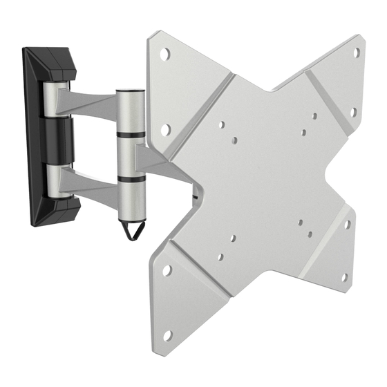
Wandhalterung für TV / Monitor
Bitte überprüfen Sie VOR der Montage den Lochabstand zwischen den VESA Befestigungslöchern an Ihrem
!
Bildschirm!
Diese Wandhalterung unterstützt folgende Lochabstände:
Horizontal / Waagerecht
Vertikal / Senkrecht
S1822
VESA-Befestigungslöcher
Vertikal /
Senkrecht
Horizontal / Waagerecht
75mm, 100mm, 200mm
75mm, 100mm, 200mm
75x75
100x100
200x100
200x200
MONTAGEANLEITUNG
ACHTUNG: NIEMALS DAS MAXIMAL
ZULÄSSIGE BELASTUNGSGEWICHT
ÜBERSCHREITEN. MISSACHTUNG
KANN ZU SACHSCHÄDEN ODER
SCHWEREN VERLETZUNGEN FÜHREN!
Bildschirm Rückseite
20kg
(44lbs)
MAX
Deutsch
v.18.02
English
Advertisement

Related Manuals for ricoo S1822


Summary of Contents for ricoo S1822
- Page 1 Bitte überprüfen Sie VOR der Montage den Lochabstand zwischen den VESA Befestigungslöchern an Ihrem Bildschirm! VESA-Befestigungslöcher Vertikal / Senkrecht Horizontal / Waagerecht Bildschirm Rückseite Diese Wandhalterung unterstützt folgende Lochabstände: Horizontal / Waagerecht 75mm, 100mm, 200mm Vertikal / Senkrecht 75mm, 100mm, 200mm 75x75 20kg S1822 100x100 (44lbs) 200x100 200x200 Deutsch English...
- Page 2 Liebe Kundin, lieber Kunde, S1822 wir freuen uns, dass Sie sich für ein Produkt der Marke "RICOO" entschieden haben Manchmal trotz aller Bemühungen unsererseits Ihnen ein qualitativ hochwertiges Produkt zu liefern, kann es vorkommen, dass einmal ein Zubehörteil fehlt oder ein Teil während des Transports beschädigt wird...
- Page 3 Lieferumfang WICHTIG: Stellen Sie vor der Montage sicher, dass alle Teile welche hier aufgeführt sind, bei der Lieferung dabei sind. Sollten Teile fehlen oder defekt sein, kontaktieren Sie Ihren Händler. Grundgerüst (x1) Dekorative Abdeckung 1(x1) Dekorative Abdeckung 2(x1) 3mm Inbusschlüssel (x1) 4mm Inbusschlüssel (x1) Paket M M8x20 (x4)
- Page 4 1. Trennung der Frontplatte vom Grundgerüst 2a. Befestigung an der Holzbalkenwand 50mm (2") ø 4mm (ø 5/32”) Holzbalken mit Balkenfinder finden und die Montagelöcher markieren. Montagelöcher bohren. Wandplatte an die Wand anschrauben. WARNUNG • Stellen Sie sicher, dass die Befestigungsschrauben in der Mitte der Balken verankert sind. Die Verwendung eines Balkenfinders wird dringend empfohlen.
- Page 5 2b. Befestigung an der Massivbetonwand 60mm 55mm (2.4") (2.2") ø 8mm (ø 5/16") Achtung: Mitgelieferte Dübel sind nur für Massivbeton- wände geeignet! Montagelöcher markieren. Montagelöcher bohren. Wandplatte an die Wand anschrauben. WARNUNG Installateure müssen sicher stellen, dass die Anbaufläche das Gesamtgewicht von diesem Produkt inkl. aller angeschlossener Komponente sicher tragen kann.
- Page 6 3. Montage der dekorativen Abdeckungen Montieren Sie die dekorativen Abdeckungen entlang der Wandplatte. Achten Sie darauf, dass diese auf der Wandplatte einrasten. Deutsch English...
- Page 7 4. Anbringung der Frontplatte an den Bildschirm Oberseite des TVs oder · Wählen Sie die zu Ihrem TV passenden Schrauben. · Montieren Sie die Frontplatte am Display. · Fixieren Sie die Frontplatte mit Hilfe von den dazugehörigen Schrauben. Ziehen Sie alle Schrauben nach. ACHTUNG: Nicht überziehen! Deutsch English...
- Page 8 5. Aufhängung des TV-Geräts an die Wandhalterung / das Grundgerüst Wand Wand Heben Sie das Display inkl. montierter Frontplatte an und hängen diese in das Grundgerüst der Halterung ein. Ziehen Sie alle Schrauben (welche im Schritt 1 entfernt wurden) wieder zu. 6.
- Page 9 7. Einstellungen / Ausrichtung. Fertig Je nach Gewicht des Displays, Wand kann es notwendig sein, Anpassungen an der Kugelgelenk- Vorrichtung durchzuführen. 180° 180° 180° -15° 360° +15° Die TV-Halterung kann um 180° geschwenkt, um +/-15° geneigt oder um 360° gedreht werden. Wartung •...
- Page 10 Please check BEFORE installation distance between VESA mounting holes on your display! VESA-Mounting holes Vertical / Perpendicularly Horizintally Display back This wall mount supports the following distance between holes: Horizontally 75mm, 100mm, 200mm Vertical / Perpendicularly 75mm, 100mm, 200mm 75x75 20kg S1822 100x100 (44lbs) 200x100 RATED 200x200 English Deutsch...
- Page 11 Dear customer, S1822 we are pleased that you have decided for a product of the brand "RICOO" Sometimes, despite our efforts to provide you with a high-quality product, it may happen that an accessory is missing or a part is damaged during transport .
-
Page 12: Component Checklist
Component Checklist IMPORTANT: Ensure that you have received all parts according to the component checklist prior to installation. If any parts are missing or faulty, telephone your local distributor for a replacement. articulated arm assembly(x1) wall plate cover 1(x1) wall plate cover 2(x1) 3mm Allen key (x1) 4mm Allen key (x1) Package M... - Page 13 1. Removing the VESA Plate 2a. For Wood Stud Wall Mounting 50mm (2") ø 4mm (ø 5/32”) Find and mark the exact location of mounting holes. Drill pilot holes Screw the wall mount onto the wall WARNING • Make sure that mounting screws are anchored into the center of the studs. The use of a stud finder is highly recommended. •...
- Page 14 2b. For Solid Brick and Concrete Mounting 60mm 55mm (2.4") (2.2") ø 8mm (ø 5/16") Warning: Supplied plastic anchors are only suitable for solid concrete walls! Mark the exact location of mounting holes Drill pilot holes Screw the wall mount onto the wall WARNING Installers must verify that the supporting surface will safely support the combined weight of the equipment and all...
- Page 15 3. Installing the Decorative covers I n s t a l l t h e d e c o r a t i v e c o v e r s a l o n g t h e w a l l plate rail until they snap shut onto the wall plate.
- Page 16 4. Installing the VESA Plate Top of the display Screw the VESA plate onto the display. Tighten all screws but do not over tighten. Deutsch English...
-
Page 17: Installing The Display
5. Installing the Display wall wall Lift display slowly and hook the head of VESA plate over VESA plate mount rail. Tighten screws(removed in step 1) with a proper Allen key. 6. Cable Management wall Connect the cables to your display and run the cables through the wire clip. - Page 18 7. Adjustment. Done It is necessary to slightly loosen wall or tighten the adjustment screw using a proper Allen key according to the weight of display installed. 180° 180° 180° -15° +15° 360° Adjust to the desired position or tilt. Maintenance •...
Need help?
Do you have a question about the S1822 and is the answer not in the manual?
Questions and answers