Table of Contents
Advertisement
Quick Links
Description
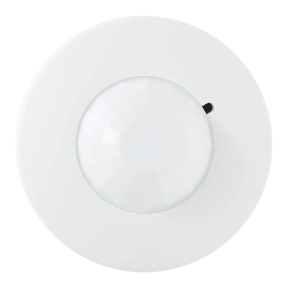
PIR10EMS - Passive infrared ceiling mount sensors with Auxiliary Contacts for connection to Energy Management Systems.
PIR10S - Passive infrared ceiling sensor slave unit
Both supplied with mounting ring, screws and masking kit.
Features
• Covers area up to 1500 sq ft when mounted at 9 ft
• Fully adjustable time delay for 30 seconds to 30 minutes including override capability. (EMS model only)
• Fully adjustable ambient light level override (5 foot candles to 200 foot candles/bypass) (EMS model only)
• Fully adjustable sensitivity (20%-100% of maximum coverage)
• A total of 6 PIR10 sensors may be controlled by a single power/switch pack (1-EMS, 5 auxiliaries)
Pre-installation
1. For installation by a qualified electrician in accordance with national and local codes and the following instruction.
2. For indoor use only
3. CAUTION: RISK OF ELECTRIC SHOCK. Disconnect power before installing. Never wire energized electrical components.
4. CAUTION: USE COPPER CONDUCTORS ONLY.
5. Check to see that the device type and rating is suitable for the application.
6. When installing the sensor, observe the maximum rated capacity of the associated power pack:
• 211-1 20A Incandescent (2400w Fluorescent) at 277VAC, 60 Hz.
• 213-1 20A Ballast (5000W Fluorescent) at 277VAC, 60Hz.
7. If moisture or condensation is evident, allow the product to dry completely before installation.
8. Do not install if any damage to the product is noticed.
Installation
1. CAUTION: Turn power off at the circuit breaker before installing power pack and sensor.
2. PIR10EMS and PIR10S sensors may be mounted directly to plaster or a drop ceiling using the metallic-mounting ring provided. They may also be mounted
using a 3-0" mud/plaster ring attached to a 4" sq. junction box. Verify local and state codes.
3. Wire the PIR10EMS and PIR10S according to the wiring diagram below. Note: Each auxiliary connection must be individually capped with acceptable wire nuts
if not used.
• RED lead (+24VCD) on PIR10EMS connects to RED lead on power/switch pack.
• BLACK lead (common) on PIR10EMS connects to BLACK lead on power/switch pack.
• WHITE/RED lead (+24 VDC to auxiliary) on PIR10EMS connects to WHITE/RED on PIR10S
• WHITE/BLACK lead (common to auxiliary) on PIR10EMS connects to WHITE/BLACK on PIR10S
• WHITE/BLUE lead (signal from auxiliary) on PIR10EMS connects to WHITE/BLUE on PIR10S
• The ORANGE, YELLOW and GREEN leads on the PIR10EMS connect to the building energy management system.
Coverage and Placement
Passive infrared sensors are activated by changes in temperature within the sensor field of view. PIR series sensors feature a 360-degree field of view with a radius
of 22 feet mounted at 8 feet. It is necessary that the unit be installed within the line of sight of the occupants. If obstructions such as partitions, furniture or plants
are present, the sensor will not see past them. The sensor should NOT be installed if:
• In view of direct sunlight or strong reflected light sources
• In direct view of open doorways where hallway traffic may accidentally activate the lights.
• Near a shower or steam source, or where exposed to rain.
• Outside (PIR10 sensors are for indoor use only)
Unit Controls and Adjustment
For all controls, maximum adjustment is clockwise (CW); minimum adjustment is counter-clockwise (CCW). Adjustment should be made after a three-minute stabi-
lization period. Make sure all fixtures and furniture is in place before adjusting any sensor. To access controls, remove the sensor cover by turning clockwise. Restore
power to the lighting circuits and turn the lights on.
Sensitivity (PIR10EMS and PIR10S)
1. Set the time delay (TIME) to minimum (Fully CCW)
2. Set the sensitivity (SENS) to maximum (Fully CW)
3. Replace the sensor cover.
4. Turn the ambient setting to maximum (Fully CW) by inserting the screwdriver through the hole in the sensor cover.
5. Move away from the sensor and stand still. The lights should switch OFF after 30 seconds. If the lights remain on, move further away from the sensor or out of
sight of the unit. If the lights still remain ON, decrease the sensitivity (SENS) by rotating it CCW. Repeat step 5.
6. Adjust as necessary. Cover must be in place for accurate reading.
1
701 Millennium Blvd. | Greenville, SC 29607 | (864) 678-1000 | (866) 898-0131 - fax www.hubbellcontrolsolutions.com
Copyright © 2020 Hubbell Control Solutions, a division of Hubbell Lighting, Inc. All rights reserved. All product and company names,
logos and product identifiers are trademarks ™ or registered trademarks ® of Hubbell Lighting, Inc. or their respective owners.
Use of them does not necessarily imply any affiliation with or endorsement by such respective owners.
Low Profile Passive Infrared Ceiling Sensor
PIR 10
INSTALLATION GUIDE
1306B 01282020
Advertisement
Table of Contents

Summary of Contents for Hubbell PIR 10 Series
- Page 1 701 Millennium Blvd. | Greenville, SC 29607 | (864) 678-1000 | (866) 898-0131 - fax www.hubbellcontrolsolutions.com Copyright © 2020 Hubbell Control Solutions, a division of Hubbell Lighting, Inc. All rights reserved. All product and company names, logos and product identifiers are trademarks ™ or registered trademarks ® of Hubbell Lighting, Inc. or their respective owners.
- Page 2 701 Millennium Blvd. | Greenville, SC 29607 | (864) 678-1000 | (866) 898-0131 - fax www.hubbellcontrolsolutions.com Copyright © 2020 Hubbell Control Solutions, a division of Hubbell Lighting, Inc. All rights reserved. All product and company names, logos and product identifiers are trademarks ™ or registered trademarks ® of Hubbell Lighting, Inc. or their respective owners.


Need help?
Do you have a question about the PIR 10 Series and is the answer not in the manual?
Questions and answers