Advertisement
INSTALLATION, OPERATION & MAINTENANCE DATA SHEET
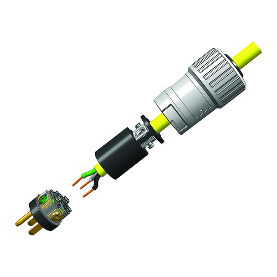
THE ACCEPTOR SERIES "UGP" & "UGP(QW)" PLUGS
IMPORTANT: These plugs must be installed by trained,
qualified and competent personnel.
NOTE: All installations must comply with applicable local
and/or national electrical codes, as well as safety practices
for this type of equipment.
WARNING: Electrical power must be OFF during
installation. Disconnect supply circuit and Lock Out.
CAUTION: To reduce the risk of ignition of hazardous
atmospheres, do not use in Class II, Group F locations that
contain electrically conductive dusts.
Before install, check the carton label and product
nameplate to be sure you have the correct type.
DIRECTIONS FOR INSTALLATION
UGP
: For use with Killark Type "UGR" receptacles and
other receptacles specified on Form No. K1092, also
provided with this product.
1.) Loosen (2) screws (with lockwashers) "A" in plug face
and pull Plug Contact Assembly (with gasket) from Plug
Body. NOTE: Fiber insulator should remain in Plug Body.
Loosen (2) screws "B" at back of plug to remove Cord
Clamp Cover.
2.) Strip cord jacket and wire insulation from #12 or #14 (as
required) AWG type S, SO, ST or STO cord, per strip gage
shown below. Cord diameter must be .540 to .635 inches.
Do not use cord of smaller diameter.
3.) Loosen (2) Cord Clamp screws "C" and feed cord,
prepared end first, through Cord Clamp Cover and Cord
Clamps. Lubricate approximately 1-1/2" of prepared end of
cord jacket with a suitable lubricant and insert cord through
sealing Grommet into Plug Body.
4.) Loosen all (3) Wire Terminal screws and insert wire into
proper terminals: Green lead (Ground) to terminal by Green
mark; White (Neutral) lead to terminal by White mark (125V
only); Black and/or Red [Line lead(s)] to unmarked
terminal(s). Hand tighten terminal screws to 8 in.lbs.
torque.
5.) Check to make sure fiber insulator is installed in Plug
Body. Properly align the Plug Contact Assembly (with
gasket) and slide Plug Body down over contact assembly
until seated. Insert (2) screws and lockwashers "A" and
tighten to 8 in.lbs. torque.
6.) Tighten Cord Clamp screws "C", alternating between
them to equalize torque. Tighten until clamps firmly grip
cord to prevent movement.
7.) Position Cord Clamp Cover; insert and tighten (2)
screws "B". Check for ground continuity between ground
post and plug body. Check for discontinuity between live
spade contacts and/or plug body.
P/N KIL00921377 FORM NO. K1377 R11/17 ECO-7-028-17
HUBBELL ELECTRICAL PRODUCTS
A Division of HUBBELL INCORPORATED (Delaware)
3940 Martin Luther King Drive
St. Louis, Missouri 63113 USA
UGP
[QW model, side 2]
Side 1 of 2
Advertisement
Table of Contents

Subscribe to Our Youtube Channel
Related Manuals for Hubbell KILLARK ACCEPTOR UGP Series


Summary of Contents for Hubbell KILLARK ACCEPTOR UGP Series
- Page 1 HUBBELL ELECTRICAL PRODUCTS A Division of HUBBELL INCORPORATED (Delaware) 3940 Martin Luther King Drive St. Louis, Missouri 63113 USA INSTALLATION, OPERATION & MAINTENANCE DATA SHEET THE ACCEPTOR SERIES "UGP" & "UGP(QW)" PLUGS IMPORTANT: These plugs must be installed by trained, qualified and competent personnel.
- Page 2 DIRECTIONS FOR INSTALLATION UGP(QW) : For use with Killark Type "UGR" receptacles and other receptacles specified on Form No. K1092, also provided with this product. 1.) Loosen (2) screws "A" in plug face and pull Plug Contact Assembly (with gasket) from the Plug Body. Remove Insulator Assembly from Plug Body.
- Page 3 use, and assumes all risk and liability whatsoever in connection therewith. P/N KIL00921377 FORM NO. K1377 R11/17 ECO-7-028-17 Side 3 of 2...
Need help?
Do you have a question about the KILLARK ACCEPTOR UGP Series and is the answer not in the manual?
Questions and answers