Johnson & Johnson DePuy Synthes Battery Power Line II User Manual
Battery-driven power tool system for orthopedics and traumatology
Hide thumbs
Also See for DePuy Synthes Battery Power Line II:
- Instructions for use manual (76 pages)

Subscribe to Our Youtube Channel
Related Manuals for Johnson & Johnson DePuy Synthes Battery Power Line II


Summary of Contents for Johnson & Johnson DePuy Synthes Battery Power Line II
- Page 1 Battery-driven power tool system for orthopedics and traumatology Battery Power Line II User’s Manual...
-
Page 2: Table Of Contents
Table of Contents Introduction General Information Drive Units Operating Instructions Universal Battery Charger II Battery Pack (battery casing with inserted battery) Battery Reamer/ Drill II Attachments for Battery Reamer/ Drill II Battery Oscillator II Battery Reciprocator II Care and Maintenance General Information Preparation Prior to Cleaning Manual Cleaning Instructions... - Page 3 Table of Contents Troubleshooting System Specifications Electromagnetic Compatibility Ordering Information Warning: This description alone does not provide sufficient background for the direct use of the product. Instruction by a surgeon experienced in handling this product is highly recommended. Battery Power Line II User’s Manual DePuy Synthes Power Tools...
-
Page 4: General Information
Introduction General Information Intended Use The Battery Power Line II is a heavy duty battery-driven system intended for orthopedic and trauma applications including: • Drilling • Reaming • Inserting/removing Kirschner wires and pins • Cutting bone Battery Reamer/ Drill II Drilling Reaming Kirschner wire insertion... - Page 5 Introduction General Information Battery Oscillator II Oscillating sawing Battery Reciprocator II Reciprocating sawing Battery Power Line II User’s Manual DePuy Synthes Power Tools...
- Page 6 Introduction General Information Safety Instructions Cutting tools must be cooled with irrigation fluid to The Battery Power Line II (BPL II) is only to be used prevent heat necrosis. for patient treatment after careful consultation of the The user of the product is responsible for proper use instructions for use.
- Page 7 Introduction General Information Notes • Always wear personal protective equipment (PPE) including safety goggles when handling the BPL II system. • To avoid injuries, the locking mechanism of the tool has to be activated before every manipulation and when laying the tool down (i.e. the mode switch has to be in the off position).
- Page 8 Introduction General Information Accessories/Scope of Delivery Storage and Transport The Battery Power Line II consists of three different Only use the original packaging for dispatch and transport handpieces, a battery casing, a battery, and a range of as otherwise damage may occur. If this is not possible, attachments designed for the system.
- Page 9 Introduction General Information Explanation of Symbols The following symbols are applied to the device or individual components. SAFE Caution This symbol indicates that this battery contains rechargeable lithium-ion cells. The battery is rechargeable. Consult the provided instructions for use before operating the device. Duty cycle type according to IEC 60034-1.
-
Page 10: Drive Units
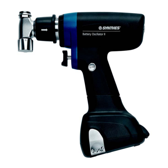
Introduction Drive Units Battery Reamer/ Drill II (530.705) Speed (without attachment) 0– 340 rpm (maximum speed varies with attachment) Torque (without attachment) 0– 15 Nm (maximum torque varies with attachment) Weight of handpiece (including battery pack) 1565 g/3.4 lb Cannulation 4.0 mm diameter Protection against electric shock Protection against water ingress... - Page 11 Introduction Drive Units Battery Oscillator II (530.710) Speed 0 – 12,000 oscillations per minute Deflection 4.5° (0° + /-2.25°) Weight of handpiece (including battery pack) 1685 g/3.7 lb Protection against electric shock Protection against water ingress IP X 4 Technical data is subject to tolerances. Saw head Mode switch Saw blade coupling...
- Page 12 Introduction Drive Units Battery Reciprocator II (530.715) Speed 0– 14,000 oscillations per minute Stroke 4 mm Weight of handpiece (including battery pack) 1675 g/3.6 lb Protection against electric shock Protection against water ingress IP X 4 Technical data is subject to tolerances. Mode switch Saw head Saw blade coupling...
- Page 13 Introduction Drive Units Battery for Battery Power Line II (530.630) Type Li-Ion (lithium ion) Voltage 14.8 V Capacity 1.5 Ah/ 22.2 Wh Charging time Typically <60 minutes Technical data is subject to tolerances. Note: For further information on the correct method of charging, storing and using the battery, please refer to page 17.
-
Page 14: Universal Battery Charger Ii
Operating Instructions Universal Battery Charger II Front View The Universal Battery Charger II (05.001.204) includes four independent charging bays. Each charging bay has three slots; the Battery Power Line II battery (530.630) fits into the top slot. Note: For the BPL II battery to be recognized and charged by the UBC II, firmware version 14.0* is required. -
Page 15: Battery Pack
Operating Instructions Battery Pack (battery casing with inserted battery) DePuy Synthes non-sterile batteries and advanced charging technology optimize intraoperative battery capacity, maximize battery lifespan, and shorten turnaround time. One Universal Battery Charger II (05.001.204) for multiple DePuy Synthes battery-driven systems simplifies the charging process. - Page 16 Operating Instructions Battery Pack Circulating Person Circulating person Insert the non-sterile battery through the insertion shield into the battery casing (Figure 5a). Press down on the battery to ensure it is fully seated (Figure 5b). Note: The shape of the battery ensures that it is inserted with the correct pole alignment.
- Page 17 Operating Instructions Battery Pack Scrubbed Person Close the battery casing (Figures 7a and 7b). Note: Ensure that both battery casing locks engage and that the lid of the battery casing is closed properly. Always ensure that the lid of the battery casing is totally closed before using the system.
- Page 18 Operating Instructions Battery Pack Removing and Disassembling the Battery Pack Press both release buttons simultaneously on the drive unit to remove the battery pack (Figure 9). Open the casing by pressing both battery casing locks and remove the battery or hold open the battery casing to allow another person to remove the battery (Figure 10).
- Page 19 Operating Instructions Battery Pack Charging, Storing, and Using Batteries Do not expose batteries to heat or fire. Avoid storage in direct sunlight. Charging Keep the charger and the batteries clean and in a cool Only use the DePuy Synthes Universal Battery Charger II and dry place.
- Page 20 Operating Instructions Battery Pack Notes • Generally, medical power tools can heat up if in constant use. The cool down times should be observed; see “Duty Cycle” section on page 71, to prevent the power tool from exceeding its acceptable surface temperature.
- Page 21 Operating Instructions Battery Reamer/Drill II (530.705) For clockwise rotation, turn the mode switch to the “FWD” position. For counterclockwise rotation, turn the mode switch to the “REV” position. The single variable-speed trigger allows control of the speed from 0 to the maximum rpm. Maximum torque and speed vary, depending on the attachment (see page 21).
-
Page 22: Battery Reamer /Drill Ii
Operating Instructions Attachments for Battery Reamer/Drill II Instrument 530.705 Battery Reamer /Drill II Precaution: To prevent injuries, the mode switch of the drive unit should always be in the “OFF” position when inserting or removing attachments and cutting tools. Please observe the safety instructions and warnings stated in the instructions when working with attachments. - Page 23 Operating Instructions Attachments for Battery Reamer/ Drill II Color Marking on the Attachments Some rotating attachments are available in two different speeds for drilling and reaming, respectively. The attachments are marked accordingly (Figures 1 and 2). Figure 1: Chuck with drilling speed Drill Attachments (text DRILL and blue color marking) Blue color marking and inscribed with DRILL.
- Page 24 Operating Instructions Attachments for Battery Reamer/ Drill II The following notes apply to all attachments. Precautions • Always turn the mode switch to “OFF” position when inserting/removing attachments and cutting tools. • If the attachment does not engage properly then rotate the attachment gently until the drive shaft engages.
- Page 25 Operating Instructions Attachments for Battery Reamer/ Drill II Drill Chuck with Key, Drill Speed (530.730) Drill Chuck with Key, Ream Speed (530.732) • Maximum speed: – Drilling: approx. 930 rpm Drill Chuck (530.730) – Reaming: approx. 340 rpm • Maximum torque: –...
- Page 26 Operating Instructions Attachments for Battery Reamer/ Drill II Drill Chuck, Keyless, Drill Speed (530.731) • Maximum speed: approx. 930 rpm • Maximum torque: approx. 6.0 Nm • Cannulation: 3.2 mm diameter • Accepts round and triangular shafts up to 7.3 mm diameter Technical data is subject to tolerances.
- Page 27 Operating Instructions Attachments for Battery Reamer/ Drill II AO / ASIF™ Quick Coupling for Drill Bits, Drill Speed (530.750) • Maximum speed: approx. 930 rpm • Maximum torque: approx. 6.0 Nm • Cannulation: 2.0 mm diameter • Accepts cutting tools and instruments with an AO/ASIF quick coupling fitting Technical data is subject to tolerances.
- Page 28 Operating Instructions Attachments for Battery Reamer/ Drill II Quick Coupling for DHS/DCS Triple Reamers, Drill Speed (530.760) • Maximum speed: approx. 930 rpm • Maximum torque: approx. 6.0 Nm • Cannulation: 3.2 mm diameter • Accepts cutting tools and instruments with a large quick coupling fitting.
- Page 29 Operating Instructions Attachments for Battery Reamer/ Drill II Drilling/Reaming Attachments • Maximum speed: – Drilling: approx. 930 rpm – Reaming: approx. 340 rpm • Maximum torque: – Drilling: approx. 6.0 Nm – Reaming: approx. 15 Nm • Cannulation: – Drilling: 3.2 mm diameter –...
- Page 30 Operating Instructions Attachments for Battery Reamer/ Drill II Drilling/ Reaming Attachments (continued) Insert Instrument Pull back the collar of the attachment and insert the instrument, turning it slightly to align the instrument (Figure 1). Release the collar, pulling lightly on the instrument to ensure it is secure.
- Page 31 Operating Instructions Attachments for Battery Reamer/ Drill II AO / ASIF Quick Coupling for Reamers, Reaming Speed (530.780) • Maximum speed: approx. 340 rpm • Maximum torque: approx. 15 Nm • Cannulation: 4.0 mm diameter • Accepts cutting tools and instruments with an AO reaming fitting, including intramedullary reaming shafts with the AO reaming fitting Technical data is subject to tolerances.
- Page 32 Operating Instructions Attachments for Battery Reamer/ Drill II Quick Coupling for Kirschner Wires and for Pins, Drill Speed (530.791) • Maximum speed: approx. 930 rpm • Maximum torque: approx. 6.0 Nm • Cannulation: 4.0 mm diameter • Allows insertion and removal of Kirschner wires and guide pins with diameters from 1.5 mm to 4.0 mm diameter, in any length Technical data is subject to tolerances.
- Page 33 Operating Instructions Attachments for Battery Reamer/ Drill II Quick Coupling for Pins, Drill Speed (530.796) • Maximum speed: approx. 930 rpm • Maximum torque: approx. 6.0 Nm • Cannulation: 3.2 mm diameter • Dedicated attachment to fix knee replacement cutting blocks with a pin (as shown on page 3) •...
- Page 34 Operating Instructions Attachments for Battery Reamer/ Drill II Radiolucent Drive (511.300) and Assemble Radiolucent Drive Adapter for Radiolucent Drive (530.741) Insert the Adapter for Radiolucent Drive into the Battery • Maximum speed: approx. 1,100 rpm Reamer/Drill II. • Maximum torque: approx. 1.3 Nm Slide the Radiolucent Drive over the Adapter and twist Technical data is subject to tolerances.
- Page 35 Operating Instructions Attachments for Battery Reamer/ Drill II Insert Drill Bits 1. Pull the ring on the Radiolucent Drive forward and push the drill bit into the coupling as far as it can go while rotating it slightly (Figure 1). 2.
- Page 36 Operating Instructions Attachments for Battery Reamer/ Drill II Using the Radiolucent Drive (continued) Notes • Grip the coupled Radiolucent Drive tightly when switching on the power tool, particularly if the power tool is held face down. • Only special 3-flute spiral drill bits can be used. Your DePuy Synthes representative will be glad to provide you with additional information on which drill bits can be used.
-
Page 37: Battery Oscillator
Operating Instructions Battery Oscillator II (530.710) To operate the drive unit, turn the mode switch to the “ON” position. The single variable-speed trigger allows control of the oscillating frequency from 0 to 12,000 oscillations per minute. When the trigger is released, the power tool stops immediately. - Page 38 Operating Instructions Battery Oscillator II (530.710) Insert Saw Blade Fully open the saw blade coupling by turning the locking knob. Insert an oscillating saw blade into the coupling. Turn the locking knob in the opposite direction to secure the saw blade. Tighten the locking knob (Figure 1). Adjust Sawing Plane Pull the sliding sleeve back and rotate the saw head to adjust the sawing plane (adjustable through 360°...
-
Page 39: Battery Reciprocator
Operating Instructions Battery Reciprocator II (530.715) To operate the drive unit, turn the mode switch to the “ON” position. The single variable-speed trigger allows control of the reciprocating frequency from 0 to 14,000 oscillations per minute. When the trigger is released, the tool stops immediately. - Page 40 Operating Instructions Battery Reciprocator II (530.715) Insert Saw Blade Insert a reciprocating saw blade into the coupling and push until the saw blade locks in place (Figure 1). Lightly pull the saw blade to ensure it is properly seated. Adjust Sawing Plane Pull the sliding sleeve back and rotate the saw head to adjust the sawing plane (adjustable through 360°...
-
Page 41: General Information
Care and Maintenance General Information • Detergents used on the products will be in contact Power tool units and attachments are frequently exposed with the following materials: stainless steel, to high mechanical loads and shocks during use and should not be expected to last indefinitely. Proper aluminum, plastic, and rubber seals. -
Page 42: Preparation Prior To Cleaning
Care and Maintenance Preparation Prior to Cleaning Disassembly Before cleaning, remove all instruments and attachments from the power tool. Remove the battery casing from the handpiece and then remove the battery itself. To clean the battery and the charger, wipe them off with a clean, soft, lint-free cloth dampened with disinfectant or deionized water (Figures 1 and 2). -
Page 43: Manual Cleaning Instructions
Care and Maintenance Manual Cleaning Instructions 1. Remove Debris Rinse the device under running cold tap water for a minimum of 2 minutes. Use a sponge, soft, lint-free cloth or soft-bristled brush to assist in removing gross soil (Figure 1). For cannulations of the handpiece and attachments, the cleaning brush (516.101) should be used. - Page 44 Care and Maintenance Manual Cleaning Instructions 4. Clean with Detergent Clean the device manually under running warm water using an enzymatic cleaner or detergent for a minimum of 5 minutes. Manipulate all moving parts under running water. Use a soft-bristled brush and/ or soft, lint-free cloth to remove all visible soil and debris (Figures 3 and 4).
- Page 45 Care and Maintenance Manual Cleaning Instructions 5. Rinse with Tap Water Rinse the device thoroughly using cool to lukewarm running water for a minimum of 2 minutes. Use a syringe or pipette to flush lumens and channels. Actuate joints, handles and other movable device features in order to rinse thoroughly under running water.
-
Page 46: Automated Cleaning Instructions With Manual Precleaning
Care and Maintenance Automated Cleaning Instructions with Manual Precleaning Notes • Manual precleaning prior to automated cleaning is important to ensure cannulations and other difficult to access areas are clean. • Alternative cleaning procedures other than in the procedure described below (including manual precleaning) have not been validated by DePuy Synthes. - Page 47 Care and Maintenance Automated Cleaning Instructions with Manual Precleaning 2. Manipulate Moving Parts Manipulate all moving parts such as triggers, sliding sleeves, attachment release rings, saw blade coupling, and switches under running tap water to loosen and re- move gross debris. 3.
- Page 48 Care and Maintenance Automated Cleaning Instructions with Manual Precleaning 7. Load DePuy Synthes Washing Basket Please use the specially designed tray for machine washing as supplied by DePuy Synthes (68.001.620, 68.001.625). Follow the numbered loading plan as shown on pages 47 and 48.
- Page 49 Care and Maintenance Automated Cleaning Instructions with Manual Precleaning 68.001.620 Washing Basket Full size ¹⁄ ¹ 530.705 510.191 Battery Reamer/Drill II or Key for Drill Chuck BPL Attachments 530.690 530.660 530.605 Battery Reamer/Drill (530.730 and 530.732) (BPL, BPL II) Battery Casing Insertion Shield Two spots for 530.790, 530.791.
- Page 50 Care and Maintenance Automated Cleaning Instructions with Manual Precleaning 68.001.625 Washing Basket size ½ 530.690 Battery Casing 530.715 Battery Reciprocator II, or BPL II: 530.705 Battery Reamer/Drill II, or 530.710 Battery Oscillator II BPL: 530.605 Battery Reamer/Drill, or 530.610 Battery Oscillator, or 530.660 530.615 Battery Reciprocator Insertion Shield...
- Page 51 Care and Maintenance Automated Cleaning Instructions with Manual Precleaning 8. Automated Cleaning Cycle Parameters Note: The washer/disinfector should fulfill requirements specified in ISO 15883. Minimum Duration Cleaning Step (minutes) Instructions Rinse Cold tap water Prewash Warm water (≥ 40 °C); use detergent Clean Warm water (≥...
-
Page 52: Lubrication
Care and Maintenance Lubrication To ensure a long service life and smooth operation, it is recommended that the accessible moving parts of the handpiece, battery casing, and attachment are lubricated after each use with one drop of Synthes Special Oil (519.97). Spread the oil by moving the components. - Page 53 Care and Maintenance Lubrication Battery Reamer/ Drill II (530.705) The following individual parts must be lubricated with one drop of Synthes Special Oil (519.97): 1. Attachment release ring (Figures 1a and 1b) 2. Trigger shaft 3. Rear end of the cannulation (Figure 3) Turn the attachment release ring clockwise and insert one drop of Synthes Special Oil (519.97) as shown in Figure 1a.
- Page 54 Care and Maintenance Lubrication Battery Oscillator II (530.710) The following individual parts must be lubricated with one drop of Synthes Special Oil (519.97): 1. Saw blade coupling 2. Locking knob for the saw blade quick coupling 3. Sliding sleeve for positioning the saw blade (Figures 1a and 1b) 4.
- Page 55 Care and Maintenance Lubrication Battery Reciprocator II (530.715) The following individual parts must be lubricated with one drop of Synthes Special Oil (519.97): 1. Saw blade coupling 2. Sliding sleeve for positioning the saw blade (Figures 1a and 1b) 3. Trigger shaft Pull the sliding sleeve back and put one drop of Synthes Special Oil (519.97) on the exposed area (Figure 1a).
- Page 56 Care and Maintenance Lubrication Lubricating the Battery Casing (530.690) Place oil on the complete inside edge of the battery casing and distribute it evenly. Open and close the lid several times to lubricate the sealing. Wipe off excess oil with a cloth (Figure 1).
- Page 57 Care and Maintenance Lubrication Lubricating the Attachments After each use, lubricate all moving parts of the attachment with one drop of Synthes Special Oil (519.97) (Figures 1a and 1b). Spread the oil by moving the components. Wipe off excess oil with a cloth. Insert one drop of Synthes Special Oil (519.97) in the gap between the seal ring and shaft of the attachment coupling...
-
Page 58: Inspection And Function Test
Care and Maintenance Inspection and Function Test Instructions Visually inspect for damage and wear. Check the handpiece controls for smooth operation and function. All movable parts should be moving smoothly. Check that the triggers do not remain blocked in the handpiece when pressing on them. -
Page 59: Packaging, Sterilization, And Storage
Care and Maintenance Packaging, Sterilization, and Storage Packaging Put cleaned and dry products into their proper places in the DePuy Synthes VARIO CASE (689.202 Figures 1a – 1d) or the DePuy Synthes Washing Basket (68.001.620, 68.001.625 Figures 1a and 1b). Additionally, use an appropriate sterilization wrap or reusable rigid container system for sterilization, such as a Sterile Barrier System according to ISO 11607. - Page 60 • If the Washing Basket (68.001.620, 68.001.625) is sterilized in a rigid container, the lid (68.001.602, 68.001.604) is not required. DePuy Synthes Battery Power Line II system may be resteril- ized using validated steam sterilization methods (ISO 17665 or national standards). DePuy Synthes recommendations...
- Page 61 Care and Maintenance Packaging, Sterilization and Storage Storage Storage conditions for products labeled “STERILE” are printed on the packaging label. Packaged and sterilized products should be stored in a dry, clean environment, protected from direct sunlight, pests, and extremes of temperature and humidity. Use products in the order in which they are received (“first-in, first-out principle“), taking note of any expiration date on the label.
-
Page 62: V-Pro 1
Care and Maintenance ® ® STERRAD and V-PRO Systems Sterilization Guide For Li-Ion Battery (530.630) 1. Preparation Prior to Reprocessing Before cleaning, remove all instruments and attachments from the power tool. Remove the battery casing from the handpiece and then remove the battery from the battery casing. - Page 63 Care and Maintenance ® ® STERRAD and V-PRO Systems Sterilization Guide 6. Storage and Use Battery can be used immediately or sterile stored in accor- dance with the hospital’s procedures. Rotate stock and recharge unused batteries, as necessary. Compared to nickel based batteries the self-discharge rate of the BPL II Li-Ion battery is less than half during storage Notes:...
- Page 64 Care and Maintenance ® ® STERRAD and V-PRO Systems Sterilization Guide ® ® 7. STERRAD or V-PRO Sterilized Battery Insertion • The scrubbed person performs all of the steps according to Figure 1–8 • Open the lid of the battery casing (530.690) by simultaneously pressing both battery casing locks (Fig.
-
Page 65: Repairs And Technical Service
Care and Maintenance Repairs and Technical Service The power tool should be sent to the DePuy Synthes office for repair if it is faulty or malfunctions. Contaminated products have to run through the complete reprocessing procedure before being sent to the DePuy Synthes office for repair or technical service. -
Page 66: Disposal Of Waste
Care and Maintenance Disposal of waste In most cases, faulty power tools can be repaired (refer to the previous section “Repairs and Technical Service”). Please send devices that are no longer used to your local DePuy Synthes representative. This ensures that they are disposed of in accordance with the national application of the respective directive. - Page 67 Troubleshooting General Problem Possible Causes Solution Drive unit does not start No battery in the drive unit Insert charged battery Battery is discharged Charge or replace battery Battery is defect Replace battery Drive unit is defect Send drive unit to DePuy Synthes service center Drive unit did not cool down Allow to cool to room temperature...
- Page 68 Troubleshooting General (continued) Problem Possible causes Solution Drive unit or attachment Drive unit or attachment is used outside Allow drive unit or attachment to cool. becomes excessively hot the specification (see Duty cycles on page 68) The cutting tool is blunt Replace the cutting tool Visible physical damage Battery was accidentally reprocessed...
- Page 69 Troubleshooting Battery Reamer /Drill II Problem Possible Causes Solution Precaution: Immediately turn mode Attachments cannot couple Coupling is blocked by residue to drive unit switch OFF (Lock position). Remove solid particles with pickups. Clean and lubricate according to care and maintenance guidelines.
- Page 70 Troubleshooting Battery Reciprocator II Problem Possible Causes Solution Precaution: Immediately turn mode Attachments cannot couple Coupling is blocked by residue to drive unit switch OFF (Lock position). Remove solid particles with pickups. Clean and lubricate according to care and maintenance guidelines. Attachment coupling is damaged Send damaged attachment to DePuy Synthes service center...
- Page 71 Troubleshooting Troubleshooting Attachments and Cutting Tools (continued) Problem Possible Causes Solution Cutting tool is difficult to The attachment or cutting tool is deformed Replace the attachment or cutting tool, or couple or cannot be coupled from wear send it to a DePuy Synthes service center to an attachment Attachment becomes Attachment is used too long...
- Page 72 System Specifications The Device meets the Following “Standards” EN 60601-1/IEC 60601-1/ EN 60601-1-2/IEC 61000-6-1/ IEC 61000-6-2 /IEC 61000-6-3 IEC 61000-6-4 10PB Medical electrical devices With regard to electrical shock, fire and mechanical hazards only in accordance with EN 60601-1 and ANSI/ AAMI ES60601-1 (2005) and CAN/CSA C22.2 No.
- Page 73 System Specifications Duty Cycle Precautions • Carefully observe the recommended duty cycles. Intermittent operation type S9, according to IEC 60034-1 • Duty cycles can be reduced due to higher loads applied and due to ambient temperatures above 20 °C (68 °F). Xs on Ys off •...
- Page 74 System Specifications Declaration of the emission sound pressure level and the sound power level according to EU Directive 2006 /42 /EC Measurement of the sound pressure level (LpA) is carried out in accordance with standard EN ISO 11202. Measurement of the sound power level (LwA) is carried out in accordance with standard EN ISO 3746.
- Page 75 System Specifications Declaration of vibration emission according to EU Directive 2002/44/ EC Vibration emissions [m/ s ] tested according to EN ISO 5349-1. Maximum Daily Maximum Daily Exposure Time to Exposure Time Declaration Reach Limit Value to Reach Limit Handpiece Attachment Cutting Tool [m /s...
- Page 76 Electromagnetic Compatibility Accompanying Documents According to IEC 60601-1-2, 2007, Clause 6 Table 1: Emissions Guidance and manufacturer’s declaration— electromagnetic emissions The Battery Power Line (BPL) or Battery Power Line II (BPL II) System is intended for use in the electromagnetic environment specified below.
- Page 77 Electromagnetic Compatibility Accompanying Documents According to IEC 60601-1-2, 2007, Clause 6 Table 2: Immunity (all devices) Guidance and manufacturer’s declaration— electromagnetic immunity The BPL or BPL II System is intended for use in the electromagnetic environment specified below. The customer or the user of BPL or BPL II System should ensure that it is used in such an environment.
- Page 78 Electromagnetic Compatibility Accompanying Documents According to IEC 60601-1-2, 2007, Clause 6 Table 4: Immunity (not life-supporting devices) Guidance and Manufacturer’s Declaration — Electromagnetic Environment—Guidance Electromagnetic Immunity Portable and mobile RF communications equipment The BPL or BPL II System is intended for use in the should be used no closer to any part of the BPL or BPL II electromagnetic environment specified below.
- Page 79 Electromagnetic Compatibility Accompanying Documents According to IEC 60601-1-2, 2007, Clause 6 Table 6: Recommended separation distances (not life-supporting devices) Recommended Separation Distances Between Portable and Mobile RF Communications Equipment and the BPL or BPL II System The BPL or BPL II System is intended for use in the electromagnetic environment in which radiated RF disturbances are controlled.
- Page 80 Ordering Information Drive units 530.780 AO /ASIF Quick Coupling for Reamers, 530.705 Battery Reamer /Drill II for Battery Power Line 530.710 Battery Oscillator II 530.791 Quick Coupling for Kirschner Wires and 530.715 Battery Reciprocator II for Pins 1.5 mm– 4.0 mm diameter 530.796 Quick Coupling for Pins 3.2 mm diameter Charger, battery, and accessories for battery...
- Page 81 Ordering Information Example Battery Power Line II Set— Example Battery Power Line II Set— Joint Replacement Trauma Instruments Instruments 05.01.204 Universal Battery Charger II 05.01.204 Universal Battery Charger II 530.705 Battery Reamer /Drill II 530.705 Battery Reamer/Drill II 530.710 Battery Oscillator II 530.710 Battery Oscillator II 530.715...
- Page 82 Notes DePuy Synthes Power Tools Battery Power Line II User’s Manual...
- Page 83 Notes Battery Power Line II User’s Manual DePuy Synthes Power Tools...
- Page 84 Disclaimer: Please refer to the package insert(s) or other labeling associated with the devices identified in this brochure for additional information. Some devices in this brochure may not have been licensed in accordance with Canadian law and may not be for sale in Canada. Please contact your sales consultants for items approved for sale in Canada.
Need help?
Do you have a question about the DePuy Synthes Battery Power Line II and is the answer not in the manual?
Questions and answers