
Subscribe to Our Youtube Channel
Related Manuals for YOKOGAWA F3LH02-0N


Summary of Contents for YOKOGAWA F3LH02-0N
- Page 1 User’s Manual YHLS Master Module IM 34M6H46-01E Applicable Modules: Model Code Model Name F3LH02-0N YHLS Master Module IM 34M6H46-01E 1st Edition Yokogawa Electric Corporation...
-
Page 3: Applicable Product
Document No. IM 34M6H46-01E Document Model Code DOCIM IM 34M6H46-01E 1st Edition : Nov. 1, 2005-00 Media No. IM 34M6H46-01E (CD) 1st Edition : Nov. 1, 2005-00 (AR) All Rights Reserved Copyright 2001, Yokogawa Electric Corporation... -
Page 4: Important
- Every effort has been made to ensure accuracy in the preparation of this manual. However, should any errors or omissions come to the attention of the user, please contact the nearest Yokogawa Electric representative or sales office. Safety Precautions when Using/Maintaining the Product - The following safety symbols are used on the product as well as in this manual. - Page 5 WARRANTY that is provided separately. - Yokogawa Electric assumes no liability to any party for any loss or damage, direct or indirect, caused by the use or any unpredictable defect of the product.
- Page 6 - Reverse engineering, such as decompiling of the software, is strictly prohibited. - No portion of the software supplied by Yokogawa Electric may be transferred, exchanged, or sublet or leased for use by any third party without prior permission by Yokogawa Electric.
- Page 7 General Requirements for Using the FA-M3 Controller Avoid installing the FA-M3 controller in the following locations: - Where the instrument will be exposed to direct sunlight, or where the operating temperature exceeds the range 0°C to 55°C (32°F to 131°F). - Where the relative humidity is outside the range 10 to 90%, or where sudden temperature changes may occur and cause condensation.
- Page 8 Keep spare parts on hand: - Stock up on maintenance parts including spare modules, in advance. Discharge static electricity before operating the system: - Because static charge can accumulate in dry conditions, first touch grounded metal to discharge any static electricity before touching the system. Never use solvents such as paint thinner for cleaning: - Gently clean the surfaces of the FA-M3 controller with a cloth that has been soaked in water or a neutral detergent and wringed.
-
Page 9: Introduction
Introduction Overview of the Manual This manual describes the specifications, operations, and communications protocol of the YHLS (Yokogawa High-speed Link System) master module F3LH02-0N. Related Instruction Manuals The manuals to be read depend on the CPU module to be used. -
Page 10: Copyrights And Trademarks
Registering or recording onto videotapes and other media is also prohibited without expressed permission of Yokogawa Electric Corporation. Trademarks - The trade and company names that are referred to in this document are either trademarks or registered trademarks of their respective companies. -
Page 11: Table Of Contents
TOC-1 FA-M3 YHLS Master Module IM 34M6H46-01E 1st Edition CONTENTS Applicable Product ..................i Important ....................ii Introduction.....................vii Copyrights and Trademarks ..............viii Overview ..................1-1 What is YHLS? ..................1-1 Features of YHLS..................1-1 1.2.1 Communications between Sequence CPU Module and Slave Units ................1-1 1.2.2 Withdrawal of Slave Unit ............ - Page 12 TOC-2 Withdrawal of Slave Unit ................ 3-3 Automatic Slave Unit Participation............3-4 Stopping Communications when CPU Stops........3-4 Monitoring Slave Units for Error............3-4 Response Time................4-1 Remote Scan time (RST) ............... 4-1 Response Time ..................4-3 Communication Preparation Flow ..........5-1 List of I/O Relays ................
-
Page 13: Overview
Overview The Yokogawa High-speed Link System (YHLS) master module F3LH02-0N has two YHLS master interface ports for connecting slave units to perform remote I/O. Table 1.1 Applicable Module Model Code Module Name F3LH02-0N YHLS Master Module What is YHLS? Yokogawa High-speed Link System (YHLS) is designed for implementing high-speed remote I/O in an FA-M3 system. -
Page 14: Constant Communication Cycle Time
1.2.4 Constant Communication Cycle Time YHLS features a constant communication cycle time, not affected by automatic participation or withdrawal of slave units, thus delivering reliable communications with constant cycle time under all circumstances. 1.2.5 Control of YHLS Output States when CPU Stops If the sequence CPU module switches to STOP mode, the YHLS master module also stops communications with the slave units. -
Page 15: Specifications
12 Mbps max., 2 YHLS ports Operating Environment There is no restriction on the type of CPU module that can be used with the F3LH02-0N module. The F3LH02-0N module may be installed in the main unit but not in a sub-unit. -
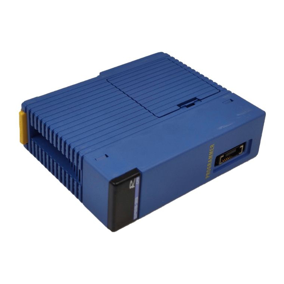
Page 16: Components And Functions
Components and Functions Front View Status indicators RDY: Lit when the internal circuit is functioning normally. YHLS communication ports LNK: Lit during communication with slave units. ALM: Lit at communication failure. LED Indicators Designation Description When Lit When Not Lit (color) Internal circuit RDY (green) -
Page 17: External Connection
External Connection Connection Topology YHLS master module Slave Slave Slave Slave Slave Slave unit unit unit unit unit unit Port Slave Slave Slave Slave Slave Slave unit unit unit unit unit unit Port Each port supports a maximum of 63 slave units. Maximum transmission speed: 12 Mbps (at 100 m distance) Maximum transmission distance: 300 m (at 3 Mbps) Connector Pin Assignment... -
Page 18: Cables
Cables Prepare a plug-cable set that complies with the connector pin assignment described above. Use cables of the type described below. CAT5 shielded cable or equivalent - Shielded twisted-pair cable - Impedance: 100 Ω - Conductor size: AWG24 CAUTION - If a different type of cable is recommended for a slave unit by its manufacturer, use that cable instead. -
Page 19: Attaching/Detaching The Module
Attaching/Detaching the Module Attaching the Module Figure 2.2 shows how to attach this module to the base module. First hook the anchor slot at the bottom of the module to be attached onto the anchor pin on the bottom of the base module. - Page 20 Attaching the Module in Intense Vibration Environments If the module is used in intense vibration environments, fasten the module with a screw. Use screws of type listed in the table below. Insert these screws into the screw holes on top of the module and tighten them with a Phillips screwdriver.
-
Page 21: Functions
Functions This chapter describes the functions of the YHLS master module. List of Functions Table 3.1 List of Functions Functions Description Section: I/O communication with slave units for ON/OFF control and Communication with slave units monitoring. A slave unit that failed to communicate due to power off or any other reason is withdrawn from the network and Withdrawal of slave unit communication continues with the remaining normal slave... -
Page 22: Communication With Slave Units
Communication with Slave Units 3.2.1 Starting Communications After setting the transmission speed, communications mode and the slave unit last address for the YHLS master module, turn on the Request to Communicate relay start communication between YHLS master module and the slave units. 3.2.2 Input Input statuses of slave units are transmitted to the YHLS master module and stored in its... -
Page 23: Withdrawal Of Slave Unit
Withdrawal of Slave Unit A slave unit that is no longer available for communication due to power off or any other reason is withdrawn from the network and communication continues with the remaining normal slave units. Error YHLS master module Slave Slave Slave... -
Page 24: Automatic Slave Unit Participation
Before using this function, you should set the output at CPU failure to ‘RESET’ in the DIO setup for the slot installed with the F3LH02-0N master module in the configuration setup of the CPU module. The output condition (reset or hold) of a slave unit when the YHLS master module suspends communication depends on the Reset/Hold setting for the slave unit. -
Page 25: Response Time
Response Time This chapter describes the response time of a remote I/O system. Sequence CPU processing time Remote scan time SequenceCPU YHLS master Slave unit module module Input data Internal Read Commu- Input instruction area nication devices Internal Output Commu- Write Output devices... - Page 26 Calculation example: Suppose that 16 slave units are connected to a port for communication at 6 Mbps. Slave unit last address = 16 Tbps 1/transmission speed = 1/6 Mbps = 0.167 x 10 Thus, RST = 354 x 16 x 0.167 x 10 = 944 x 10 (seconds) Slave unit withdrawal or automatic slave unit participation does not affect the remote scan time.
-
Page 27: Response Time
Response Time The response time of a remote I/O system is the sum of the CPU scan time, remote scan time and slave unit internal processing time. Response time for output from CPU module to slave unit The output response time is the maximum time delay before an output of a slave unit turns on after the corresponding internal device of the sequence CPU module turns on. - Page 28 Calculation example Let us calculate the output response time from the CPU module to slave units under the following conditions: Number of slave units Output processing time of slave unit 1 ms max. Sequence CPU scan time 1 ms Master module transmission speed and mode 12 Mbps, full-duplex Slave Slave...
-
Page 29: Communication Preparation Flow
Communication Preparation Flow The following flowchart shows how to prepare for communications. Start Install the YHLS master module See Section 2.3, on the base module. "Attaching/Detaching the Module." Connect slave units to the YHLS See Section 2.2, master module. "External Connection." See Section 7.3, Set up the transmission speed. - Page 30 Blank Page...
-
Page 31: List Of I/O Relays
List of I/O Relays The YHLS master module has 32 input and 32 output relays for interfacing with the sequence CPU module. Each of the input relays can be set to raise an interrupt. Output Relays Table 6.1 Output Relays Output Relay Description Output Relay Name... -
Page 32: Input Relays
Input Relays Table 6.2 Input Relays Input Relay Number Input Relay Name Description Turns on when communication is started by Communicating 33. Turns off when Y 33 is turned off. Turns on when communication is started if one or Link more slave units are available for communication. -
Page 33: List Of Registers
List of Registers The YHLS master module has registers for interfacing with the sequence CPU module. They are grouped into the following four areas: Input data area : For storing data read from slave units Output data area : For storing data to be written to slave units Parameter setup area : For YHLS parameter setup Parameter monitoring area... -
Page 34: Input Data Area
Input Data Area Data position No. For port 1 For port 2 Slave 1 Slave 1 Input data area Input data area Slave 2 Slave 2 for port 1 Slave 3 Slave 3 Slave 4 Slave 4 Input data area Output data area for port 2 Reserved... -
Page 35: Output Data Area
Output Data Area Data position No. For port 1 For port 2 Slave 1 Slave 1 Output data area Input data area Slave 2 Slave 2 for port 1 Slave 3 Slave 3 Slave 4 Slave 4 Output data area Output data area for port 2 Reserved... -
Page 36: Parameter Setup Area
Parameter Setup Area Data position No. For port 1 For port 2 Last address Last address Transmission Transmission speed speed Parameter setup Input data area area for port 1 535 Communications Communications mode mode Reserved Reserved Parameter setup Output data area area for port 2 Monitored slave Monitored... -
Page 37: Last Address
7.3.1 Last Address The Last Address parameter specifies the maximum slave unit address value that can be specified for communication. It must be between 1 and 63. If the specified last address is beyond this range, it is assumed to be 63. CAUTION - A slave unit whose address is larger than the specified last address cannot be specified for communication with the master module and, therefore, its input/output... -
Page 38: Monitored Slave List
7.3.4 Monitored Slave List You can specify which slave units are to be monitored for communication error. To monitor error for a specific slave unit, set its corresponding bit to 1. Bit values for slave units beyond the Last Address setting are ignored. When a communication error with a monitored slave unit is detected, the ALM LED lights up and the ALARM relay turns on. -
Page 39: Parameter Monitoring Area
Parameter Monitoring Area Data position No. For port 1 For port 2 Last address Last address Transmission Transmission Parameter Input data area speed speed monitoring area Communications Communications for port 1 mode mode Reserved Reserved Parameter monitoring area Output data area for port 2 Alive slave list Alive slave list... -
Page 40: Last Address
7.4.1 Last Address This parameter monitors the last address setting for the current communication cycle. 7.4.2 Transmission Speed This parameter monitors the transmission speed setting for the current communication cycle. 7.4.3 Communications mode This parameter monitors the communications mode setting for the current communication cycle. -
Page 41: Failed Slave List (Latched)
7.4.6 Failed Slave List (latched) If an error is detected during communication with a slave unit specified for error monitoring, its corresponding bit in the Failed Slave List (latched) is set to 1. Once turned on, a bit is not reset to 0 even when the error condition is removed. To reset a bit, you must overwrite the bit with 0 using a program. - Page 42 Blank Page...
-
Page 43: Troubleshooting
Troubleshooting This chapter describes how to troubleshoot communication failure and other problems. Hardware or Setup Error? Check for the following setup errors before proceeding with troubleshooting: - Are the modules installed correctly? - Are the conditions set correctly? - Is the communication cable correct? - Is the YHLS master module configured correctly? - Are the settings on slave units correct? - Are the power supplies of slave units correct? -
Page 44: Troubleshooting Common Problems
Troubleshooting Common Problems This section shows troubleshooting flowcharts for various error scenarios that may occur when using the YHLS master module. Error Is sequence CPU Remove the cause of the error module in error? of the sequence CPU module. See Subsection 8.2.1, Is RDY LED lit? "RDY LED is not Lit."... -
Page 45: Rdy Led Is Not Lit
8.2.1 RDY LED is not Lit RDY LED is not lit. Is power supply module Apply proper voltage. supplied with proper voltage? Is RDY LED on power Replace the power supply module. supply module lit? Check total current consumption. Is RDY LED on If it is within the specification, other modules lit? replace the base module. -
Page 46: Lnk Led Is Not Lit
8.2.2 LNK LED is not Lit LNK LED is not lit. Is Request to Turn on Communicate the Request to Communicate relay. relay on? Is Communicating Replace the YHLS master module. relay on? Check power supply and cable Is LINK relay on? connection of slave units. -
Page 47: No Output To Slave Unit
8.2.4 No Output to Slave Unit No output to a slave unit. Check the cable from the YHLS master module. Is LINK relay on? Check the power supply of the slave unit. Note: If the LINK relay is off, it means that no slave unit is available for communication. - Page 48 Blank Page...
-
Page 49: Sample Program
Assuming 8 slave units with 16 inputs or outputs are connected The sample program below assumes that the F3LH02-0N YHLS master module is installed in slot 3 of the main unit, and four slave units (having addresses 1 to 4) with 16 outputs and four slave units (having addresses 5 to 8) with 16 inputs are connected to port 1 of the master module. - Page 50 ***Check for alive slave units*** Alive Slave List ***Check for error slave units*** * Check for slave units currently not communicating * Failed Slave List (non-latched) * Check for slave units that were not communicating at some point in time * Failed Slave List (latched) ***Clear latched error status before starting communications***...
-
Page 51: Appendix Preparing A Plug-Cable Set
Appx.-1 Appendix Preparing a Plug-cable Set (1) Modular plug, material and tool The following types of modular plug, material and tool are recommended for use: Modular plug - RJ-45 shielded-modular plug Conductive tape Example: Manufacturer: Tyco Electronics AMP K.K. Model: 5-569550-3 Guide Note: The constructions of some products may differ from the example shown here. - Page 52 Appx.-2 (3) How to prepare a plug-cable set Peel off 25-mm length of outer insulation from the cable. Take care not to damage the tape Tape shield shield underneath. Check whether the tape shield has its outer Outer insulation surface insulation-coated. 25 mm If insulation-coated: Fold the exposed part of the tape shield...
- Page 53 Appx.-3 Lead the wires and the drain into the guide and trim to about 12 mm long. Guide Pin 1: Not used Pin 2: Not used Pin 3: Twisted pair Pin 4: 12 mm Pin 5: Twisted pair Pin 6: Pin 7: Not used Pin 8: Drain Note: The two modular plugs to be installed on the...
- Page 54 Appx.-4 Crimp the plug with a modular-plug crimping tool, all the while taking care that the wires and the drain are properly positioned. The cable is now provided with a plug. Check the prepared plug-cable set for wrong connection, shorted circuit or open circuit using an ohmmeter or some other appropriate instrument.
-
Page 55: Index
Index FA-M3 YHLS Master Module IM 34M6H46-01E 1st Edition INDEX shield treatment ........... 2-4 slave units per module, number of....... 2-1 stopping communications when CPU stops ..3-4 automatic slave unit participation ....1-1, 2-1 cable ..........2-1, 2-4, App.-1 transmission distance .......... 2-1 CAT5 cable ............2-4 transmission speed.. - Page 56 Blank Page...
-
Page 57: Revision Information
Date Revised Item Nov, 2005 New publication Written by PLC Center Yokogawa Electric Corporation Published by Yokogawa Electric Corporation 2-9-32 Nakacho, Musashino-shi, Tokyo, 180-8750, JAPAN Printed by Kohoku Publishing & Printing Inc. IM 34M6H46-01E 1st Edition : Nov. 1, 2005-00... - Page 58 Blank Page...
Need help?
Do you have a question about the F3LH02-0N and is the answer not in the manual?
Questions and answers