KROHNE OPTISWIRL 4200 Supplementary Instructions Manual
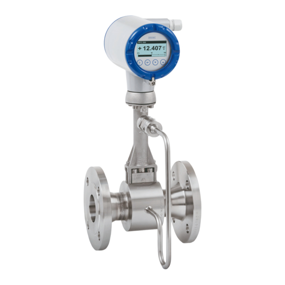
Vortex flowmeter
Hide thumbs
Also See for OPTISWIRL 4200:
- Handbook (124 pages) ,
- Quick start manual (32 pages) ,
- Supplementary instructions manual (32 pages)
Table of Contents
Advertisement
Quick Links
Advertisement
Table of Contents

Related Manuals for KROHNE OPTISWIRL 4200


Summary of Contents for KROHNE OPTISWIRL 4200
- Page 1 OPTISWIRL 4200 OPTISWIRL 4200 OPTISWIRL 4200 OPTISWIRL 4200 Supplementary instructions Supplementary instructions Supplementary instructions Supplementary instructions Vortex flowmeter Category II 2G, EPL Gb © KROHNE 05/2015 - 4004274301 - MA OPTISWIRL 4200-Exi-II2G-AD R01 en...
-
Page 2: Table Of Contents
4.5 Measuring sensor circuits (remote version only) ............19 5 Operation 5.1 Start-up........................... 21 5.2 Operation ........................21 5.3 Electrostatic charge ....................... 21 6 Service 6.1 Maintenance ........................22 6.2 Dismantling ........................22 www.krohne.com 05/2015 - 4004274301 - MA OPTISWIRL 4200-Exi-II2G-AD... -
Page 3: Safety Instructions
The "X" after the certificate number refers to special conditions for safe use of the device, which have been listed in these instructions. If needed, the IEC certificate can be downloaded from the manufacturer's website. 05/2015 - 4004274301 - MA OPTISWIRL 4200-Exi-II2G-AD www.krohne.com... -
Page 4: Security Information
The operator respectively his agent is responsible to follow further standards, directives or laws if required due to operating conditions or place of installation. This applies particularly for the use of easy detachable process connections such as SMS or Clamp when measuring flammable mediums. www.krohne.com 05/2015 - 4004274301 - MA OPTISWIRL 4200-Exi-II2G-AD... -
Page 5: Device Description
* positions which are not needed are omitted (no blank positions) The remote version consisting of the OPTISWIRL 4000 F measuring sensor and the VFC 200 F signal converter is called the OPTISWIRL 4200 F. 05/2015 - 4004274301 - MA OPTISWIRL 4200-Exi-II2G-AD... -
Page 6: Marking
The details relevant to explosion protection are identical on both nameplates. 1 Device version OPTISWIRL 4200 C or VFC 200 F ... 020 / OPTISWIRL 4000 F 2 Production order number... -
Page 7: Flammable Products
Definition of zone 1 acc. to EN 1127-1, Appendix B:An area in which an explosive atmosphere may occasionally occur as a result of the mixture of flammable substances in the form of gas, steam or mist with air under normal operation. 05/2015 - 4004274301 - MA OPTISWIRL 4200-Exi-II2G-AD www.krohne.com... -
Page 8: Protection Types
The classification is outlined in the following tables. The tables take into account the following parameters: • Ambient temperature T • Product temperature T • Nominal size DN • Heat resistance of the connecting cable www.krohne.com 05/2015 - 4004274301 - MA OPTISWIRL 4200-Exi-II2G-AD... - Page 9 The permitted ambient temperature range is indicated on the nameplate; depending on the device version it is T = -40...+65°C / -40...+149°F The minimum product temperature is -40°C / -40°F. 05/2015 - 4004274301 - MA OPTISWIRL 4200-Exi-II2G-AD www.krohne.com...
- Page 10 DN15 … 25 392 392 DN40 … 50 392 383 DN80 … 100 392 329 DN150 ... 300 392 392 1 Permanent service temperature of connecting cable and cable entry min. 176°F www.krohne.com 05/2015 - 4004274301 - MA OPTISWIRL 4200-Exi-II2G-AD...
- Page 11 DN15 … 25 392 392 DN40 … 50 392 392 DN80 … 100 392 392 DN150 ... 300 392 392 1 Permanent service temperature of connecting cable and cable entry min. 176°F 05/2015 - 4004274301 - MA OPTISWIRL 4200-Exi-II2G-AD www.krohne.com...
- Page 12 Maximum permissible product and ambient temperatures per temperature class in °F Temperature class in °F Nominal size DN15 … 25 DN40 … 50 DN80 … 100 DN150 ... 300 1 Permanent service temperature of connecting cable and cable entry min. 176°F www.krohne.com 05/2015 - 4004274301 - MA OPTISWIRL 4200-Exi-II2G-AD...
- Page 13 DN15 … 25 248 248 DN40 … 50 248 248 DN80 … 100 248 248 DN150 ... 300 248 248 1 Permanent service temperature of connecting cable and cable entry min. 176°F 05/2015 - 4004274301 - MA OPTISWIRL 4200-Exi-II2G-AD www.krohne.com...
-
Page 14: Electrical Data
Piezo / Temperature sensor circuit (connector X2.7 .. X2.12 • U = 6,65 V • I = 21 mA • P = 35 mW • C = 2,6 µF • L = 0,5 mH www.krohne.com 05/2015 - 4004274301 - MA OPTISWIRL 4200-Exi-II2G-AD... -
Page 15: Installation
• Loosen the 1 hexagon socket screw. • Turn the signal converter and connection box. • Screw base to signal converter and the connection box once again. 1 Allen screws M4 on connection housing 05/2015 - 4004274301 - MA OPTISWIRL 4200-Exi-II2G-AD www.krohne.com... -
Page 16: Special Conditions
Lock on electronics and terminal compartment Lock on electronics and terminal compartment Lock on electronics and terminal compartment The electronics and terminal compartment may be opened in hazardous areas when measuring and carrying out adjustments. www.krohne.com 05/2015 - 4004274301 - MA OPTISWIRL 4200-Exi-II2G-AD... -
Page 17: Electrical Connections
Ex ia IIC or Ex ib IIC. The bus connections are designed for connection to a certified, intrinsically safe circuit, protection type: intrinsic safety Ex ia IIC or Ex ib IIC according to the FISCO model. 05/2015 - 4004274301 - MA OPTISWIRL 4200-Exi-II2G-AD www.krohne.com... -
Page 18: Grounding And Equipotential Bonding
PA connection in the converter's terminal compartment or via the external PA connection. Ground connection remote version 1 Electrical grounding connection on measuring sensor 2 Electrical grounding connection on signal converter housing www.krohne.com 05/2015 - 4004274301 - MA OPTISWIRL 4200-Exi-II2G-AD... -
Page 19: Measuring Sensor Circuits (Remote Version Only)
• The terminal compartments of the measuring sensor circuits are supplied with a bridge between the internal PA connection and the terminal with the designation "gnye". This connection must not be separated. 05/2015 - 4004274301 - MA OPTISWIRL 4200-Exi-II2G-AD www.krohne.com... - Page 20 4 Filler wire pair shielding (protected with heat shrink tubing) 5 Fork clamp pair shielding signal converter side 6 Heat shrink tubing The measuring sensor circuit is designed in protection type intrinsically safe Ex ia II C. www.krohne.com 05/2015 - 4004274301 - MA OPTISWIRL 4200-Exi-II2G-AD...
-
Page 21: Operation
• spraying of electrons (e.g. in the vicinity of electrostatic painting systems). • pneumatically conveyed dust is exposed. CAUTION! Electrostatic charging of the housing surface by friction must be avoided. The devices must not be dry cleaned. 05/2015 - 4004274301 - MA OPTISWIRL 4200-Exi-II2G-AD www.krohne.com... -
Page 22: Service
The display can be rotated in 90° increments. It is connected to the connector pictured on the next page. Exchanging the converter insert It is permitted to replace the entire VFC 200 converter insert with a version identical in construction. www.krohne.com 05/2015 - 4004274301 - MA OPTISWIRL 4200-Exi-II2G-AD... - Page 23 In the case of environmentally critical or hazardous products, appropriate safety precautions • must be taken with regard to residual liquids in the measuring unit. New gaskets have to be used when re-installing the device in the piping. • 05/2015 - 4004274301 - MA OPTISWIRL 4200-Exi-II2G-AD www.krohne.com...
- Page 24 Measuring systems for the marine industry Head Office KROHNE Messtechnik GmbH Ludwig-Krohne-Str. 5 47058 Duisburg (Germany) Tel.:+49 203 301 0 Fax:+49 203 301 103 89 info@krohne.com The current list of all KROHNE contacts and addresses can be found at: www.krohne.com...
Need help?
Do you have a question about the OPTISWIRL 4200 and is the answer not in the manual?
Questions and answers