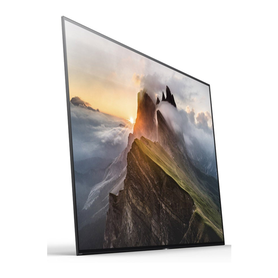
SERVICE MANUAL *Table of contents is on the last page. Please also utilize "Bookmarks“ function / "Find" function on Acrobat PDF data. A1E Series ORIGINAL MANUAL ISSUE DATE: 3/2017 GN3TR CHASSIS KA Segment Version Date Subject 3/2017 Original manual issue.
MODEL LIST MODEL COLOR COMMANDER DEST. MODEL COLOR COMMANDER DEST. XBR-55A1E Black RMF-TX201U (UC2) US/CND (LA1) MEXICO RMF-TX200B (LA8) CHILE PERU VENEZUELA XBR-65A1E Black RMF-TX201U (UC2) US/CND (LA1) MEXICO RMF-TX200B (LA8) CHILE PERU VENEZUELA XBR-77A1E Black RMF-TX201U (UC2) US/CND (LA1) MEXICO XBR-55/65/77A1E...
Components identified by shading and ! mark on the schematic diagrams, exploded views, and in the parts list are critical for safe operation. Replace these components with Sony parts whose part numbers appear as shown in this manual or in supplements published by Sony. Circuit adjustments that are critical for safe operation are identified in this manual.
Page 4
Les composants identifi es par une trame et par une marque du fonctionnement. Ne les remplacer que par des composants Sony dont le numero de piece est indique dans le present manuel ou dans des supplements publies par Sony. Les reglages de circuit dont l’importance est critique pour la securite du fonctionnement sont identifi es dans le present manuel.
Page 5
WARNINGS AND CAUTIONS CAUTION FOR THE OLED PANEL Handling When repairing the TV set, be sure you are grounded by using a wrist band. *Do not press on the panel or frame edge to avoid the risk of electric shock. *Do not scratch or press on the panel with any sharp objects.
Page 6
WARNINGS AND CAUTIONS OLED Screen •Although the OLED screen is made with high-precision technology and 99.99% or more of the pixels are effective, black dots may appear or bright points of light (white, red, blue, or green) may appear constantly on the OLED screen. This is a structural property of the OLED screen and is not a malfunction. •Do not push or scratch the front filter, or place objects on top of this TV set.
SAFETY CHECK-OUT After correcting the original service problem, perform the following safety checks before releasing the set to the customer: 1. Check the area of your repair for unsoldered or poorly soldered connections. Check the entire board surface for solder splashes and bridges. 2.
Page 8
SAFETY CHECK-OUT Leakage Test (To protect electric shock when customer touch the terminal.) Leakage current can be measured by V: Voltmeter or oscilloscope (r.m.s. or peak reading) Stabilized power supply instrument and isolated voltage transformer: Use too much current capacity and isolated voltage transformer does not need to use stabilized power supply equipment Specification of RMS volt meter: Input resistance >...
SELF DIAGNOSIS FUNCTION The units in this manual contain a self-diagnostic function. If an error occurs, the Smart Core Red LED will automatically begin to flash. The number of times the LED flashes translates to a probable source of the problem. A definition of the Smart Core Red LED flash indicators is listed in the instruction manual for the user’s knowledge and reference.
Page 10
SELF DIAGNOSIS FUNCTION [SELF DIAGNOSTIC SCREEN DISPLAY] Panel ON time[hour] /Panel Refresh times[times] Format of error timestamps Smart Core Red LED blinking count Ex) 100 / 20 YYMMDDhhmmss (in UTC) Example: 120823132523 -> Aug 23 2012 13:25:23 UTC SELF CHECK Error Item Error count * Only when time is set, an error timestamp is saved.
ADJUSTMENT HOW TO ENTER SERVICE MODE 1) Turn on the main power switch to place the set in standby condition. 2) Press the buttons on the remote commander as follows, and entering service mode. 3) Service mode display. Service Mode Model Information >>...
Page 12
ADJUSTMENT SOFTWARE VERSION 1) In Service Mode, select “Model Information”, press “Enter” or “→” button to enter Status Information. Main Micro Service Mode SW Version: PKG1.1.0.03.26.1.00.0 Model NVM Version: 0043 CEI Model Information >> Boot Version: V1.00000000 PQ Version: 02000001 Self diagnosis History >>...
Page 13
ADJUSTMENT Service Mode SERIAL NUMBER EDIT (1) Model Information >> 1) In “Service Mode”, select “Model Information” by pressing “↑” or “↓” button then pressing “Enter” or Self diagnosis History >> “→” button to enter inside. Video / Audio >> Panel / PQ >>...
Page 14
ADJUSTMENT SERIAL NUMBER EDIT (2) YES is selected, the input data is saved into EEPROM. Model SERIAL NUMBER EDIT is grayed out and the serial number that has been input is displayed. Status Information >> Operator will not able to edit anymore.
Page 15
ADJUSTMENT MODEL NUMBER SETTING 1) In “Service Mode”, select “Model Information” by pressing “↑” or “↓” button then pressing “Enter” or “→” button to enter inside. 2) Select “Model Number Setting” by pressing “↑” or “↓” button then pressing “Enter” or “→” button. 3) Press “↑”...
Page 16
ADJUSTMENT WB ADJUSTMENT (If necessary) In “Panel/PQ” service mode. c. To change data, press “←” or “→” button on remote commander. a. Go to “WB Adjustment” category by “↑” or “↓” button. Service Mode Back << R WB Gain <[ ]>...
Page 17
ADJUSTMENT WB DATA TRANSFER (XBR-55/65A1E) 2. In “WB/Mura/CUC data transfer”. a. Select “WB/Gamma data transfer” by pressing “↑” or “↓” button on remote. 1. In “Panel/PQ” service mode. b. To change the items, press “←” or “→” button on remote and press “Enter” button. a.
Page 18
ADJUSTMENT WB DATA TRANSFER (XBR-77A1E) 2. In “WB/Mura/CUC data transfer”. a. Select “CUC data transfer” by pressing “↑” or “↓” button on remote. 1. In “Panel/PQ” service mode. b. To change the items, press “←” or “→” button on remote and press “Enter” button. a.
USB UPDATE *Please refer to another manual “Service Procedure for Panel, Board 1: Download USB image and unzip file. and Software Change / Upgrade(P/N:98881800x)” for details. GN3TR chassis is the same as GN1T chassis basically. 2: Copy unzip file to USB memory root folder. 3: USB memory insert TV.
TROUBLE SHOOTING TRIAGE Confirm the symptom from the customer. Select that symptom from the chart. Bring all the boards and cables listed for that symptom. Follow the troubleshooting charts in the technical guides to isolate the board. Chart Color Code. RED DOT: Most likely defective part BLUE TRIANGLE: Secondary possible defective part BLACK TEXT: Board that may correct the symptom...
TROUBLE SHOOTING FLOW 1-1. NO POWER 1-2. NO POWER U-COM FAILURE No Power START Check VDD Check STBY 3.3V C506 Voltage. Check +3.3V_STBY Line (C521, CN401 #7pin) Replace C409 Is the voltage >3.0V? Between G* Board to G* Board near CN401 BKA board Harness on BKA board Check TYPE_DET...
Page 22
TROUBLE SHOOTING FLOW 1-2. NO POWER U-COM FAILURE Previous page Check P_ON_#2 CL417 or P-on ucom #pin13 Change IC401 is >3.0V? Check 12V_MON Check +12V_MAIN Line R446 Voltage. (G* board). Is the voltage >2.6V? Check P_ON_HL CL414 or P-on ucom #pin18 Change IC401 is >3.0V? Check DC_MON...
Page 23
TROUBLE SHOOTING FLOW 1-3. NO POWER DDCON/LDO DDCON CHECK START Check Check Vcc voltage Check IC402 Vcc voltage C602 D600 Change D600 C423 Is voltage >3V? Is diode alive? Is voltage >12V? Check +3.3V_STBY. G* board Check Vcc voltage Check C602 D601 Change D601...
Page 24
TROUBLE SHOOTING FLOW 1-3. NO POWER DDCON/LDO DDCONs CHECK LDOS CHECK START START Check +3.3V_DDC_OUT Check fuse Check Vcc voltage DDCON (IC403 on BKA / IC401 on DKA) F4xx / F40xx/F6xx Change Fuse C4xxx or C6xx Is fuse OK? Is voltage >3V? +3.3V_STBY (G* board) 1) Check POWER_ON P-on ucom #pin10 Check Enable pin...
Page 25
TROUBLE SHOOTING FLOW 2-1. LED BLINKING 2X (MAIN POWER ERROR) 2-time blinking Check “+12V_MAIN” at pin 8/9/10 of CN401 G* board on BKA Board, Voltage > 13.2V ? BKA board XBR-55/65/77A1E...
Page 26
TROUBLE SHOOTING FLOW 2-2. LED BLINKING 3X (DC ALERT AND AUDIO ERROR) DC_ALERT AUDIO ERROR LED 3x blinking (Audio Error) 3-time blinking (DC Alert) Power Off Check Go to NO SOUND (POWER OFF CHECK) Check “POWER_MAIN” Check “+5.0V_VBUS” at pin 8/9/10 of CN401 at C431 on BKA board Retry on B* board,...
Page 27
TROUBLE SHOOTING FLOW 2-3. LED BLINKING 4X (LED VOLTAGE ERROR/BCM ERROR) 2-4. LED BLINKING 5X (PANEL ID READ ERROR/EEPROM ERROR) *(PKG1.6.0.08.28.1.00.0005 or less) BCM_ERR/ (PKG1.6.0.08.29.1.00.0005 or later) LD_ERR 4-time blinking 5-times blinking (LED Voltage) Symptom Check Replace Check Fuse’F3200’ Replace improve “TCON_12_ON”...
Page 28
TROUBLE SHOOTING FLOW 2-5. LED BLINKING 6X (BACKLIGHT ERROR) 6-times blinking Harness / Symptom Connection High Check Voltage of Check Improvement broken Replace “G_ERR” harness/connection Harness harness at R403 on DKA board G* board to DKA/TCON Harness / improvement Connection OK Symptom Improvement Replace...
Page 29
TROUBLE SHOOTING FLOW 2-6. LED BLINKING 7X (TEMPERATURE ERROR) 2-7. LED BLINKING 8X (4KBE ERROR) 7-time blinking 8-time blinking Setting improvement circumstance is OK? Set to another Replace Retry Temperature, location, etc. DKA board Ventilation, etc. Symptom Improvement Replace BKA board, DKA board and Aging a few Panel...
Page 30
TROUBLE SHOOTING FLOW 3-1. NO SOUND No Sound Without LED 3x Select [External Inputs] AV receiver is connected [BRAVIA Sync Settings] No sound only Go to to HDMI in ? [BRAVIA Sync Control] [off] Analog RF and Digital RF ? No Sound Tuner [Speakers] setting is Change the setting to...
Page 31
TROUBLE SHOOTING FLOW 3-2. NO SOUND (POWER OFF CHECK) 3-3. NO SOUND (POWER ON CHECK) Power Off Check Power On Check Power Off Check From NO SOUND From 2.2 LED BLINKING 3X From 2.2 LED BLINKING 3X (DC ALERT AND AUDIO ERROR) *Power_AU is same as PVDD (1) DKA board (4) POWER_AU* check...
Page 32
TROUBLE SHOOTING FLOW 3-4. NO SOUND (AUDIO HP/AUDIO OUT) 3-5. NO SOUND ( TUNER) No Sound Audio No Sound with HP/Audio out normal picture [Headphone] [Sound] Headphone Volume [Headphone/Audio out] Increase Headphone Volume is set to MIN? Only RF tuner input? is set to ? Replace BKA board [Audio Out (Fixed)]...
Page 33
TROUBLE SHOOTING FLOW 3-6. NO SOUND (HDMI) No Sound Check the picture Refer to 4.4 NO PICTURE (HDMI) Does this model have Check the mode Connect Stereo minijack cable between Source and the TV, and Analog Audio In Change “HDMI/DVI Audio Source” to Auto or Analog Audio In. of Source equipment (Stereo minijack)? HDMI...
Page 34
TROUBLE SHOOTING FLOW 4-1. NO PICTURE No Picture BL_ON (L or H): IC401 #7pin BL_ON:H Check Smart Core Replace Check Got Any Normal Replace Behavior BL_ON the V by One FFC Panel Display? The BKA board (5x Blinking) on the BKA board Harness Symptom BL_ON:L...
Page 35
TROUBLE SHOOTING FLOW 4-2. NO PICTURE (VIDEO ANALOG SIGNAL PATH) No Picture Video Video Analog Signal Path No Picture Video IC1000 (Side Mini Jack) Check if input OSD Check J2601 NG (Vpp: 0V) is GREY OUT Connection, L36:CVBS3P CVBS3P OK if it is highlighted VIDEO_DET at R2631 G16:GPIO66 VIDEO2_DET...
Page 36
TROUBLE SHOOTING FLOW 4-3. NO PICTURE (TUNER) Notes: - Parts for I2C SDA line: R2800, C2803. - Parts for I2C SCL line : R2801, C2804. RF input no picture / noisy picture Check RF source cable Change RF cable and antenna and antenna, OK? Check Tuner power line: 3.3V at JL2800 = 3.3V?
Page 37
TROUBLE SHOOTING FLOW 4-3. NO PICTURE (TUNER) FOR ANALOG TUNING Analog Tuning For LA-ISDB(BR/AR), LA-T2(COL) and TW only For Other destination Notes: - Parts for IFOUT_N line : FB2801, C2807, C2826 Confirm ANT or Cable connection - Parts for IFOUT_P line : FB2802, C2808, C2825 - Parts for IFAGC line : R2838, C2827 : Insert correct signal in correct terminal.
Page 38
TROUBLE SHOOTING FLOW 4-3. NO PICTURE (TUNER) FOR DIGITAL TUNING Digital Tuning Notes: For TW/LA-ISDB-T - Parts for IFOUT_N line : FB2801, C2807, C2826 - Parts for IFOUT_P line : FB2802, C2808, C2825 - Parts for IFAGC line : R2838, C2827 For NA-ATSC(MX/UC)/JP_SKP(Opticast) : Insert correct signal in correct terminal.
Page 39
TROUBLE SHOOTING FLOW 4-4. NO PICTURE (HDMI) HDMI1 No Picture Check the below point at All lines Connector side are NG Other Input is OK Check other - Check +5V line Replace HDMI input - Check HPD line CN3603 - Check DDC lines - Check TMDS lines All Inputs are NG TMDS lines...
Page 40
TROUBLE SHOOTING FLOW 4-4. NO PICTURE (HDMI) HDMI2 No Picture Check the below point at All lines Connector side are NG Other Input is OK Check other - Check +5V line Replace - Check HPD line HDMI input CN3600 - Check DDC lines All Inputs are - Check TMDS lines Other TV set...
Page 41
TROUBLE SHOOTING FLOW 4-4. NO PICTURE (HDMI) HDMI3 No Picture Check the below point at All lines Connector side Other Input is OK are NG Check other - Check +5V line Replace HDMI input - Check HPD line CN3601 - Check DDC lines All Inputs - Check TMDS lines are NG...
Page 42
TROUBLE SHOOTING FLOW 4-4. NO PICTURE (HDMI) HDMI4 No Picture Check the below point at All lines Connector side are NG Other Input is OK - Check +5V line Replace Check other HDMI input - Check HPD line CN3602 - Check DDC lines All Inputs - Check TMDS lines are NG...
Page 43
TROUBLE SHOOTING FLOW 5. KEY SWITCH BUTTONS ERROR Side key buttons error Check harness connection between Harness connection issue BKA board and switch module Change harness between BKA board to switch module harness BKA board to switch module issue harness Resistor value [BKA] R260 : 0 [ohm]...
Page 44
TROUBLE SHOOTING FLOW 6. IR REMOTE COMMANDER ERROR IR remote commander does not respond Center white LED blinks Battery of remote commander when pushing buttons of could be weak. remote commander at close Change battery. to IR sensor. Check harness connection Harness connection between BKA board and issue...
Page 45
TROUBLE SHOOTING FLOW 7. LIGHT SENSOR ERROR Backlight level does not change when ambient light changed Setting is “ON” Check UI setting and make Check harness connection Battery of remote commander sure light sensor setting is between BKA board and could be weak.
Page 46
TROUBLE SHOOTING FLOW 8. NETWORK MALFUNCTION ETHERNET (WIRED) [Network Set-up] >[Wired Set-up] on the TV Connection Results Connection Results Connection Results BKA board Cable Connection Local Access Internet Access Failed Failed Failed Auto Check Wired Set-up Check cable BKA board Local router Proxy setting IP address setting...
Page 47
TROUBLE SHOOTING FLOW 8. NETWORK MALFUNCTION INTERNAL WIRELESS NETWORK MALFUNCTION INTERNAL WIRELESS NETWORK MALFUNCTION Wireless Network on the TV Is the Wi-Fi radio Error message or no scan result appear in strength too weak BKA board the network setting? or even No signal? Check with another Wi-Fi Access Point Hardware defect suspected...
Page 48
TROUBLE SHOOTING FLOW 9. BLUETOOTH MALFUNCTION Voice Remote doesn’t work 3D-glasses (Active) doesn’t work Bluetooth Speaker/Headphone/Headset doesn’t work Please refer Voice Remote manual Check BT antenna Home > Settings > 3D-glasses (Active) manual Connection is OK Bluetooth Settings Can read Bluetooth Speaker/Headphone/Headset operation manual Near discoverable Bluetooth Device...
BLOCK DIAGRAMS * depend on destinations. Some control lines are left out. * IR In BKA board Center Key RGBW LEDs * CAS/CI DDCs Video signal L/R Keys Light Sens. Audio signal Control Bus Gx board IR Rx Power * RF (PSU) Micro (STM8S103F2U6)
WIRE DRESSING *This page is only the information which shows each rough location. XBR-55A1E XBR-65A1E Himeron Himeron Aluminum tape 15 x 40 Aluminum tape 15 x 40 Fix only antenna cable Fix only antenna cable COMMON VA Tape(w/ Himeron) x27 VA Tape(w/ Himeron) x27 ・Fix wire ・Fix wire...
Page 59
*This page is only the information which shows each rough location. WIRE DRESSING XBR-77A1E G board VA Tape Himeron Tape Conductive Tape Fix wire (Included Himeron etc.) x25 Harness Tie x3 • Fix wire Slide Clamp Large x2 • Hold wires Slide Clamp Small x2 •...
PANEL HANDLING Catching Frame by Finger Pushing Display by Finger Move the Panel at Vertical Condition Holding Left/Right Edge Moving at Horizontal Condition is NG Not-pushing Display by Finger Pushing Display by Finger Move panel at vertical condition XBR-55/65/77A1E...
DISASSEMBLY • There are clutch in the yellow frame[ ]. Therefore please be careful in the case of the disassembly or assembly of parts. • [ ] indicates the part to disconnect or remove from the connectors or clampers. • “TOP” hereafter indicates the upper wire if the cables are bound together. 1.
Page 62
Disassembly of 2F part DISASSEMBLY 1. XBR-55A1E 1-2. LABEL, TERMINAL UNDER (HKS) NOTE: LABEL, TERMINAL UNDER (HKS) XBR-55/65/77A1E...
Page 65
DISASSEMBLY 1. XBR-55A1E 1-5. TAPE, COND 50X65(HKS) AND BRACKET, VESA (HKS) TAPE, COND 50X65(HKS) P/N: 4-694-195-01 BRACKET, VESA (HKS) 2 screws (SCREW, +PSW M4X10) P/N: 4-159-298-21 XBR-55/65/77A1E...
Page 66
DISASSEMBLY 1. XBR-55A1E 1-6. BRACKET, VESA (HKS) AND BRACKET, UNDER (HKS) BRACKET, VESA (HKS) 2 screws (SCREW, +PSW M4X10) P/N: 4-159-298-21 BRACKET, UNDER (HKS) XBR-55/65/77A1E...
Page 67
DISASSEMBLY 1. XBR-55A1E 1-7. TAPE AND AC INLET AND BRACKET, AC INLET (HKS) TAPE Screw (SCREW, +PSW M3X6 W12) P/N: 4-256-393-12 XBR-55/65/77A1E...
Page 68
DISASSEMBLY 1. XBR-55A1E 1-7. TAPE AND AC INLET AND BRACKET, AC INLET (HKS) NOTE: AC INLET BRACKET, AC INLET (HKS) 2 screws (SCREW, +PSW M3X8) P/N: 2-580-592-31 XBR-55/65/77A1E...
Page 69
DISASSEMBLY 1. XBR-55A1E 1-8. WIRE DRESSING NOTE: Forming harness before connecting. Open harness to be slight more than the following Confirm lock & not come off angle. XBR-55/65/77A1E...
Page 88
DISASSEMBLY 1. XBR-55A1E 1-25. HINGE (HKS) A AND CHASSIS, BOX A (HKS) NOTE: 4 screws (SCREW, +PSW M4X10) P/N: 4-159-298-21 CHASSIS, BOX A (HKS) HINGE (HKS) A XBR-55/65/77A1E...
Page 89
Disassembly of 1F part DISASSEMBLY 1. XBR-55A1E 1-26. COVER SP CTR A (HKS) AND COVER, PANEL CTR A (HKS) COVER SP CTR A (HKS) COVER, PANEL CTR A (HKS) 2 screws (SCREW +PSW 3X8) P/N: 7-682-948-01 XBR-55/65/77A1E...
Page 90
DISASSEMBLY 1. XBR-55A1E 1-27. COVER, PANEL TOP (L HKS) A AND COVER SP A (L HKS) COVER, PANEL TOP (L HKS) A COVER SP A (L HKS) COVER SP A (L HKS) 2 screws (SCREW +PSW 3X8) P/N: 7-682-948-01 XBR-55/65/77A1E...
Page 91
DISASSEMBLY 1. XBR-55A1E 1-28. COVER, PANEL BTM (L HKS) A Slide BRACKET SLIDER to down side. Screw (JOINT, SCREW) P/N: 4-400-043-11 NOTE: When installing the COVER PANEL COVER, PANEL BTM (L HKS) A XBR-55/65/77A1E...
Page 92
DISASSEMBLY 1. XBR-55A1E 1-29. FLAT CLAMP (S) FLAT CLAMP (S) NOTE: XBR-55/65/77A1E...
Page 111
DISASSEMBLY 1. XBR-55A1E 1-47. SHEET, THERMAL(BM) AND GUARD, SLIDE L (HKS) NOTE: SHEET, THERMAL(BM) P/N:4-549-186-01 GUARD, SLIDE L (HKS) 2 screws (SCREW +PSW 3X8) P/N: 7-682-948-01 XBR-55/65/77A1E...
Page 112
DISASSEMBLY 1. XBR-55A1E 1-48. SLIDE, CLAMP AND GUARD, SLIDE R (HKS) SLIDE, CLAMP GUARD, SLIDE R (HKS) 3 screws (SCREW +PSW 3X8) P/N: 7-682-948-01 XBR-55/65/77A1E...
Page 113
DISASSEMBLY 1. XBR-55A1E 1-49. BRACKET, SLIDE L (L HKS) AND BRACKET, SLIDE R (L HKS) BRACKET, SLIDE L (L HKS) Don’t pinch the wire 2 screws (SCREW, +LH M3X2.2 STEP (HKS)) P/N: 4-690-294-01 BRACKET, SLIDE R (L HKS) Don’t pinch the wire 2 screws (SCREW, +LH M3X2.2 STEP (HKS)) P/N: 4-690-294-01 XBR-55/65/77A1E...
Page 114
DISASSEMBLY 1. XBR-55A1E 1-50. STD BKT L (HKS) AND STD BKT R (HKS) STD BKT L (HKS) 2 screws (SCREW, +PSW M3X6 W12) P/N: 4-256-393-12 STD BKT R (HKS) 2 screws (SCREW, +PSW M3X6 W12) P/N: 4-256-393-12 XBR-55/65/77A1E...
Page 115
DISASSEMBLY 1. XBR-55A1E 1-51. FRONT SIDE FOOT (HKS) AND CUSHION 1525A 4 screws (SCREW M3X3.0 STEP) P/N: 4-579-926-01 CUSHION 1525A FRONT SIDE FOOT (HKS) *Double-sided tape on top surface XBR-55/65/77A1E...
Page 116
DISASSEMBLY 1. XBR-55A1E 1-52. CUSHION 825B AND CUSHION 825C AND SHEET, AL PCB L(HKS) CUSHION 825B CUSHION 825C SHEET, AL PCB L(HKS) SHEET, AL PCB L(HKS) P/N: 4-694-193-01 P/N: 4-694-193-01 XBR-55/65/77A1E...
Page 117
DISASSEMBLY 1. XBR-55A1E 1-53. SHEET, AL PCB S(HKS) AND TAPE, COND 50X65(HKS) AND OLED PANEL TAPE, COND 50X65(HKS) P/N: 4-694-195-01 OLED PANEL SHEET, AL PCB S(HKS) P/N: 4-694-194-01 XBR-55/65/77A1E...
Page 122
DISASSEMBLY 2. XBR-65A1E 2-5. TAPE, COND 50X65(HKS) AND BRACKET, VESA (HKS) TAPE, COND 50X65(HKS) P/N: 4-694-195-01 BRACKET, VESA (HKS) 2 screws (SCREW, +PSW M4X10) P/N: 4-159-298-21 XBR-55/65/77A1E...
Page 123
DISASSEMBLY 2. XBR-65A1E 2-6. BRACKET, VESA (HKS) AND BRACKET, UNDER (HKS) BRACKET, VESA (HKS) 2 screws (SCREW, +PSW M4X10) P/N: 4-159-298-21 BRACKET, UNDER (HKS) XBR-55/65/77A1E...
Page 124
DISASSEMBLY 2. XBR-65A1E 2-7. TAPE AND AC INLET AND SHEET, AC INLET (HKS) AND BRACKET, AC INLET (HKS) TAPE Screw (SCREW, +PSW M3X6 W12) P/N: 4-256-393-12 XBR-55/65/77A1E...
Page 125
DISASSEMBLY 2. XBR-65A1E 2-7. TAPE AND AC INLET AND SHEET, AC INLET (HKS) AND BRACKET, AC INLET (HKS) AC INLET ASSY 2 screws (SCREW, +PSW M3X8) P/N: 2-580-592-31 SHEET, AC INLET(HKS) NOTE: P/N: 4-697-561-01 AC INLET BRACKET, AC INLET (HKS) XBR-55/65/77A1E...
Page 126
DISASSEMBLY 2. XBR-65A1E 2-8. WIRE DRESSING NOTE: Forming harness before connecting. Open harness to be slight more than the following Confirm lock & not come off angle. XBR-55/65/77A1E...
Page 128
DISASSEMBLY 2. XBR-65A1E 2-9. SHEET, THERMAL (HKS G) AND CONNECTOR ASSY 28P(PWRG) AND CONNECTOR ASSY 14P(PWRB) AND G76 NOTE: 7 screws (SCREW, +PSW M3X6 W12) P/N: 4-256-393-12 XBR-55/65/77A1E...
Page 129
DISASSEMBLY 2. XBR-65A1E 2-9. SHEET, THERMAL (HKS G) AND CONNECTOR ASSY 28P(PWRG) AND CONNECTOR ASSY 14P(PWRB) AND G76 CONNECTOR ASSY 28P(PWRG) P/N:1-910-112-45 CONNECTOR ASSY 14P(PWRB) P/N:1-910-112-47 XBR-55/65/77A1E...
Page 130
DISASSEMBLY 2. XBR-65A1E 2-10. SHEET, THERMAL(HKS G B S) AND SHEET, THERMAL(HKS G B L) SHEET, THERMAL(HKS G B S) P/N: 4-694-196-01 SHEET, THERMAL(HKS G B L) P/N: 4-694-197-01 XBR-55/65/77A1E...
Page 131
DISASSEMBLY 2. XBR-65A1E 2-11. SHEET, INSULATION (HKS B) AND PLATE, G (HKS) NOTE: PLATE, G (HKS) SHEET, INSULATION (HKS B) XBR-55/65/77A1E...
Page 132
DISASSEMBLY 2. XBR-65A1E 2-12. SHEET, STUD SUPPORT(HKS) AND SHEET, INSULATION (HKS A) NOTE: SHEET, INSULATION (HKS A) SHEET, STUD SUPPORT(HKS) XBR-55/65/77A1E...
Page 146
DISASSEMBLY 2. XBR-65A1E 2-26. HINGE (HKS) A AND CHASSIS, BOX A (HKS) 4 screws (SCREW, +PSW M4X10) P/N: 4-159-298-21 CHASSIS, BOX A (HKS) HINGE (HKS) A XBR-55/65/77A1E...
Page 147
Disassembly of 1F part DISASSEMBLY 2. XBR-65A1E 2-27. GASKET COVER SP CTR (HKS) AND COVER SP CTR A (HKS) COVER SP CTR A (HKS) GASKET COVER SP CTR (HKS) P/N: 4-693-620-01 XBR-55/65/77A1E...
Page 169
DISASSEMBLY 2. XBR-65A1E 2-48. SHEET, THERMAL(BM) AND GUARD, SLIDE L (HKS) NOTE: SHEET, THERMAL(BM) P/N: 4-549-186-01 GUARD, SLIDE L (HKS) 2 screws (SCREW +PSW 3X8) P/N: 7-682-948-01 XBR-55/65/77A1E...
Page 170
DISASSEMBLY 2. XBR-65A1E 2-49. SLIDE, CLAMP AND GUARD, SLIDE R (HKS) SLIDE, CLAMP GUARD, SLIDE R (HKS) 3 screws (SCREW +PSW 3X8) P/N: 7-682-948-01 XBR-55/65/77A1E...
Page 171
DISASSEMBLY 2. XBR-65A1E 2-50. BRACKET, SLIDE L (2L HKS) AND BRACKET, SLIDE R (2L HKS) BRACKET, SLIDE L (2L HKS) Don’t pinch the wire 2 screws (SCREW, +LH M3X2.2 STEP (HKS)) P/N: 4-690-294-01 BRACKET, SLIDE R (2L HKS) Don’t pinch the wire 2 screws (SCREW, +LH M3X2.2 STEP (HKS)) P/N: 4-690-294-01 XBR-55/65/77A1E...
Page 172
DISASSEMBLY 2. XBR-65A1E 2-51. STD BKT L (HKS) AND STD BKT R (HKS) STD BKT L (HKS) 2 screws (SCREW, +PSW M3X6 W12) P/N: 4-256-393-12 STD BKT R (HKS) 2 screws (SCREW, +PSW M3X6 W12) P/N: 4-256-393-12 XBR-55/65/77A1E...
Page 173
DISASSEMBLY 2. XBR-65A1E 2-52. FRONT SIDE FOOT (HKS) AND CUSHION 1525A 4 screws (SCREW M3X3.0 STEP) P/N: 4-579-926-01 CUSHION 1525A FRONT SIDE FOOT (HKS) *Double-sided tape on top surface XBR-55/65/77A1E...
Page 174
DISASSEMBLY 2. XBR-65A1E 2-53. CUSHION 825B AND SHEET, AL PCB L(HKS) CUSHION 825B SHEET, AL PCB L(HKS) SHEET, AL PCB L(HKS) P/N: 4-694-193-01 P/N: 4-694-193-01 XBR-55/65/77A1E...
Page 175
DISASSEMBLY 2. XBR-65A1E 2-54. SHEET, AL PCB S(HKS) AND TAPE, COND 50X65(HKS) AND OLED PANEL TAPE, COND 50X65(HKS) P/N: 4-694-195-01 OLED PANEL SHEET, AL PCB S(HKS) P/N: 4-694-194-01 XBR-55/65/77A1E...
Page 185
DISASSEMBLY 4. XBR-77A1E 4-6. BRACKET, VESA (3L HKS) AND BRACKET, UNDER (HKS) BRACKET, VESA (3L HKS) 2 screws (SCREW, +PSW M4X10) P/N: 4-159-298-31 BRACKET, UNDER (HKS) XBR-55/65/77A1E...
Page 186
DISASSEMBLY 4. XBR-77A1E 4-7. CUSHION 1525A AND AC INLET AND BRACKET, AC INLET (HKS) CUSHION 1525A P/N: 4-575-746-01 Screw (SCREW, +PSW M3X6 W12) P/N: 4-256-393-12 XBR-55/65/77A1E...
Page 187
DISASSEMBLY 4. XBR-77A1E 4-7. CUSHION 1525A AND AC INLET AND BRACKET, AC INLET (HKS) NOTE: AC INLET BRACKET, AC INLET (HKS) 2 screws (SCREW, +PSW M3X8) P/N: 2-580-592-31 XBR-55/65/77A1E...
Page 188
DISASSEMBLY 4. XBR-77A1E 4-8. WIRE DRESSING NOTE: Forming harness before connecting. Open harness to be slight more than the following Confirm lock & not come off angle. XBR-55/65/77A1E...
Page 190
DISASSEMBLY 4. XBR-77A1E 4-10. WIRE DRESSING AND CONNECTOR ASSY 28P(PWRG) AND CONNECTOR ASSY 14P(PWRB) AND G77 6 screws (SCREW, +PSW M3X6 W12) P/N: 4-256-393-12 XBR-55/65/77A1E...
Page 191
DISASSEMBLY 4. XBR-77A1E 4-10. WIRE DRESSING AND CONNECTOR ASSY 28P(PWRG) AND CONNECTOR ASSY 14P(PWRB) AND G77 NOTE: 10 screws (SCREW, +PSW M3X6 W12) P/N: 4-256-393-12 XBR-55/65/77A1E...
Page 192
DISASSEMBLY 4. XBR-77A1E 4-10. WIRE DRESSING AND CONNECTOR ASSY 28P(PWRG) AND CONNECTOR ASSY 14P(PWRB) AND G77 CONNECTOR ASSY 28P(PWRG) P/N:1-910-112-51 CONNECTOR ASSY 14P(PWRB) P/N:1-910-112-47 XBR-55/65/77A1E...
Page 193
DISASSEMBLY 4. XBR-77A1E 4-11. SHEET, THERMAL(HKS G B L) AND SHEET, INSULATION(3L HKS B) AND PLATE, G(3L HKS) SHEET, THERMAL(HKS G B L) P/N: 4-694-197-01 NOTE: SHEET, INSULATION(3L HKS B) PLATE, G(3L HKS) XBR-55/65/77A1E...
Page 194
DISASSEMBLY 4. XBR-77A1E 4-12. TAPE AND CONNECTOR ASSY 3P AND SWITCH UNIT (3M-P) AND HOLDER, SIDE SW (HKS) TAPE HOLDER, SIDE SW (HKS) ASSY Screw (SCREW +PSW 3X8) P/N: 7-682-948-01 XBR-55/65/77A1E...
Page 195
DISASSEMBLY 4. XBR-77A1E 4-12. TAPE AND CONNECTOR ASSY 3P AND SWITCH UNIT (3M-P) AND HOLDER, SIDE SW (HKS) CONNECTOR ASSY 3P P/N:1-910-112-53 SWITCH UNIT (3M-P) HOLDER, SIDE SW (HKS) XBR-55/65/77A1E...
Page 196
DISASSEMBLY 4. XBR-77A1E 4-13. SHEET, THERMAL (3L HKS G) AND SHEET, INSULATION(3L HKS A) SHEET, THERMAL (3L HKS G) P/N: 4-697-263-01 NOTE: SHEET, INSULATION(3L HKS A) XBR-55/65/77A1E...
Page 208
DISASSEMBLY 4. XBR-77A1E 4-25. HINGE (3L HKS) A AND CHASSIS, BOX A (3L HKS) NOTE: 4 screws (SCREW, +PSW M4X10) P/N: 4-159-298-31 CHASSIS, BOX A (3L HKS) HINGE (3L HKS) A XBR-55/65/77A1E...
Page 209
Disassembly of 1F part DISASSEMBLY 4. XBR-77A1E 4-26. GASKET COVER SP CTR (HKS) AND COVER SP CTR A (HKS) COVER SP CTR A (HKS) GASKET COVER SP CTR (HKS) P/N: 4-693-620-01 XBR-55/65/77A1E...
Page 230
DISASSEMBLY 4. XBR-77A1E 4-46. SHEET, THERMAL(BM) AND GUARD, SLIDE L (HKS) NOTE: SHEET, THERMAL(BM) P/N: 4-549-186-01 GUARD, SLIDE L (HKS) 2 screws (SCREW +PSW 3X8) P/N: 7-682-948-01 XBR-55/65/77A1E...
Page 231
DISASSEMBLY 4. XBR-77A1E 4-47. SLIDE, CLAMP AND GUARD, SLIDE R (HKS) SLIDE, CLAMP GUARD, SLIDE R (HKS) 3 screws (SCREW +PSW 3X8) P/N: 7-682-948-01 XBR-55/65/77A1E...
Page 232
DISASSEMBLY 4. XBR-77A1E 4-48. BRACKET, SLIDE L (3L HKS) AND BRACKET, SLIDE R (3L HKS) BRACKET, SLIDE L (3L HKS) Screw (SCREW, +LH M3X2.2 STEP (HKS)) P/N: 4-690-294-01 BRACKET, SLIDE R (3L HKS) Screw (SCREW, +LH M3X2.2 STEP (HKS)) P/N: 4-690-294-01 XBR-55/65/77A1E...
Page 233
DISASSEMBLY 4. XBR-77A1E 4-49. STD BKT L (HKS) AND STD BKT R (HKS) STD BKT L (HKS) 2 screws (SCREW +FH M3X5) P/N: 4-723-252-01 STD BKT R (HKS) 2 screws (SCREW +FH M3X5) P/N: 4-723-252-01 XBR-55/65/77A1E...
Page 234
DISASSEMBLY 4. XBR-77A1E 4-50. GASKET COVER SP CTR (HKS) AND FRONT SIDE FOOT (HKS) AND CUSHION 1525A When installing the CUSHION 1525A CUSHION 1525A FRONT SIDE FOOT (HKS) *Double-sided tape on top surface GASKET COVER SP CTR (HKS) P/N: 4-693-620-01 XBR-55/65/77A1E...
Page 235
DISASSEMBLY 4. XBR-77A1E 4-51. CUSHION 825B AND SHEET, AL PCB S(HKS) AND SHEET, AL PCB(3L HKS) AND SHEET, AL PCB L(HKS) CUSHION 825B Sequence from right edge to left edge SHEET, AL PCB S(HKS) P/N: 4-694-194-01 SHEET, AL PCB L(HKS) SHEET, AL PCB L(HKS) SHEET, AL PCB(3L HKS) P/N: 4-694-193-01...
EXPLODED VIEWS • Items with no part number and no description are not stocked because they are seldom required for routine service. • The construction parts of an assembled part are indicated with a collation number in the remark column. •...
Page 238
EXPLODED VIEWS 1. XBR-55A1E G76 AND BKA REF. No. PART No. DESCRIPTION MARK 4-693-441-01 TAPE, CONDUCTIVE PG(HKS) 4-696-435-01 SHEET, STUD SUPPORT(HKS) 8-594-302-80 UNIVERSAL SIL-TU SUT-RA243ZP UC2/LA1 8-594-308-40 UNIVERSAL SIL-TU SUT-RT243ZP 1-474-647-12 SWITCH UNIT (3M-P) 4-694-915-01 CUSHION 2F HRS(HKS) 4-693-400-01 LEVER, HINGE (HKS) 4-688-522-31 BRACKET, CARD SLOT(HKS) 4-688-522-01...
Page 239
EXPLODED VIEWS 1. XBR-55A1E PANEL COVER REF. No. PART No. DESCRIPTION MARK 4-688-500-01 COVER SP A (L HKS) 4-688-476-01 COVER, PANEL TOP (L HKS) A 4-688-500-11 COVER SP A (L HKS) 4-693-842-01 FLAT CLAMP (L) 4-693-843-01 FLAT CLAMP (S) 4-688-480-01 COVER, PANEL BTM (L HKS) A 4-689-301-01 COVER, PANEL CTR A (HKS)
Page 240
EXPLODED VIEWS 1. XBR-55A1E OLED PANEL REF. No. PART No. DESCRIPTION MARK A-2188-134-A OLED PANEL(L55GKA5)(SVC) CH 4-688-734-01 FRONT SIDE FOOT (HKS) 4-688-484-01 BRACKET, SLIDE L (L HKS) A-2167-837-A DKA MOUNT 4-696-277-01 CUSHION, SPACER DKA(L HKS) 4-688-485-01 BRACKET, SLIDE R (L HKS) 4-688-748-01 BRACKET, TS (PUC) A-2181-590-A...
EXPLODED VIEWS 4. XBR-77A1E REAR COVER REF. No. PART No. DESCRIPTION MARK 4-693-752-01 COVER, TERMINAL (HKS) 4-688-523-21 BRACKET, UNDER (HKS) FOR UC2 4-688-523-01 BRACKET, UNDER (HKS) FOR LA1 1-859-224-11 SP-BOX ASSY 4-693-191-01 REAR COVER, A CB(3L HKS) 4-693-214-21 LABEL, TERMINAL UNDER (HKS) FOR UC2 4-693-214-31 LABEL, TERMINAL UNDER (HKS)
Page 249
EXPLODED VIEWS 4. XBR-77A1E G76 AND BKA REF. No. PART No. DESCRIPTION MARK 4-693-513-02 TAPE, CONDUCTIVE PG(3L HKS) 4-696-435-01 SHEET, STUD SUPPORT(HKS) 8-594-302-80 UNIVERSAL SIL-TU SUT-RA243ZP 1-474-647-12 SWITCH UNIT (3M-P) 4-694-915-01 CUSHION 2F HRS(HKS) 4-693-400-01 LEVER, HINGE (HKS) 4-688-522-01 BRACKET, CARD SLOT(HKS) FOR LA1 4-688-522-31 BRACKET, CARD SLOT(HKS)
Page 250
EXPLODED VIEWS 4. XBR-77A1E PANEL COVER REF. No. PART No. DESCRIPTION MARK 4-688-504-02 COVER SP A (2L HKS) 4-693-185-01 COVER, PANEL TOP (3L HKS) A 4-688-504-12 COVER SP A (2L HKS) 4-693-842-01 FLAT CLAMP (L) 4-693-843-01 FLAT CLAMP (S) 4-693-187-01 COVER, PANEL BTM (3L HKS) A 4-689-301-02 COVER, PANEL CTR A (HKS)
Page 251
EXPLODED VIEWS 4. XBR-77A1E OLED PANEL REF. No. PART No. DESCRIPTION MARK A-2190-400-A OLED PANEL(L77AKA3)(SVC) 4-688-734-01 FRONT SIDE FOOT (HKS) 4-693-189-01 BRACKET, SLIDE L (3L HKS) A-2167-837-A DKA MOUNT 4-693-190-01 BRACKET, SLIDE R (3L HKS) 1-522-021-12 BT ANTENNA 380MM FXC 2-650-770-21 SLIDE, CLAMP WHITE...
Page 254
EXPLODED VIEWS 5. OTHER PART MISCELLANEOUS PART No. DESCRIPTION MARK 4-548-743-01 HOLDER, HS WS (MUF) For BKA 4-549-188-01 HOLDER(HS MUF) For BKA 4-691-273-01 SHEET, NOISE REDUCTION For BKA HEAT SINK 7-600-040-44 ADHESIVE (SV380C) 333CC GRY For BKA 4-549-186-01 SHEET, THERMAL(BM) For DKA 4-575-746-01 CUSHION 1525A...
APPENDIX-1 Voice Remote Control • This remote has the following functions: • Key “MIC” key: Bluetooth • Voice search • Key codes (except “MIC” key) are sent by IR code. You can control all TVs without pairing. • “MIC” key code and voice data are sent by Bluetooth. Voice search function could be used with only the paired TV.
APPENDIX-1 Setting Voice Remote Control To register the Voice Remote Control to the TV 1. Press the HOME button, select [Settings] [Voice Remote Control] [Activate the button] then, follow the on-screen instruction. 2. Prepare Voice Remote Control. 3. Press and hold down the Volume-down key. 4.
APPENDIX-2 Reset vs. Factory Reset Reset: Press and hold down the power button (approx. 5 seconds) on the remote commander until the message “Power off” appears on the TV screen The TV will turn off, and then restart automatically Try a reset when Android TV doesn’t behave properly (e.g., the TV is unresponsive or is stuck on a black screen). Note if you unplug and plug in the power cable, it may have the same effect as a reset.
APPENDIX-3 Other parts which should be synchronously replaced when replacing a panel 77” Description 55" 65" ● ● ● 4-688-734-01 FRONT SIDE FOOT (HKS) ● ● 4-693-441-01 TAPE, CONDUCTIVE PG(HKS) ● 4-693-513-02 TAPE, CONDUCTIVE PG(3L HKS) ● ● ● 4-694-193-01 SHEET, AL PCB L(HKS) ●...
APPENDIX-5 Panel individual packing for service NOTE: As shown in a figure, please set direction of top, bottom, and the face of a panel. PANEL Top PANEL Bottom PANEL FRONT PANEL PANEL Bottom XBR-55/65/77A1E...
APPENDIX-6 The installation style of the TV set Table Top Style Wall Mount Style Stand Support Stand Wall Mount Support Plate These parts are contained in set packing. XBR-55/65/77A1E...
APPENDIX-6 Confirm HINGE lock condition Slide Slide Open Close Slide the LEVER to unlock and close/open 2F. LEVER will be automatically locked when 2F is closed/opened completely. (*Only 2 positions) Note: Open and close the 2F with the LEVER held in the red position till it is automatically released XBR-55/65/77A1E...
APPENDIX-6 Service Position and Screwdriver information A mini-screwdriver is needed for the service OP of gap area. (between 1F and 2F) 55” *ex. Since especially gap-A is narrow, refer to the following table for the mini-screwdriver dimension which can be used. Length Remarks [mm]...
APPENDIX-7 How to disassemble HEAT SINK for BKA board If you need to disassemble HEAT SINK from service board for repair, Please cut HOLDER,HS WS(MUF) with tool (nippers) from B side of board. However, please do it carefully because some damage may be given to the neighborhood parts or the board itself.
Table of contents F COVER APPENDIX-1 MODEL LIST Voice Remote Control WARNINGS AND CAUTIONS How to use voice search function SAFETY CHECK-OUT Setting Voice Remote Control SELF DIAGNOSIS FUNCTION APPENDIX-2 ADJUSTMENT Reset vs. Factory Reset USB UPDATE APPENDIX-3 TROUBLE SHOOTING Other parts which should be synchronously replaced when replacing a panel TRIAGE APPENDIX-4...
Need help?
Do you have a question about the A1E Series and is the answer not in the manual?
Questions and answers