National Instruments NI 9205 Getting Started Manual
Hide thumbs
Also See for NI 9205:
- Operating instructions manual (37 pages) ,
- Getting started manual (27 pages)

Related Manuals for National Instruments NI 9205


Summary of Contents for National Instruments NI 9205
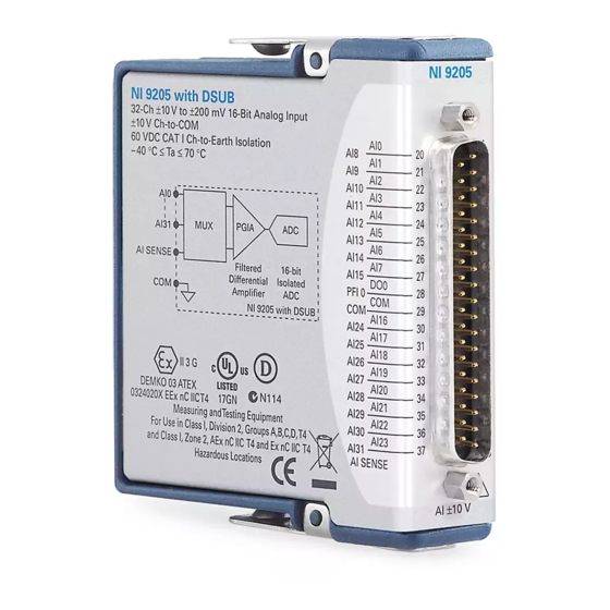
- Page 1 GETTING STARTED GUIDE NI 9205 16 AI Differential/32 AI Single-Ended, ±200 mV to ±10 V, 16 Bit, 250 kS/s Aggregate...
-
Page 2: Safety Guidelines
This document explains how to connect to the NI 9205. Before you begin, complete the software and Note hardware installation procedures in your chassis documentation. The guidelines in this document are specific to Note the NI 9205. The other components in the system might not meet the same safety ratings. -
Page 3: Safety Voltages
The maximum voltage that can be applied or output between AI and COM without creating a safety hazard. This specification is valid only up to 2,000 m. NI 9205 Getting Started Guide | © National Instruments | 3... - Page 4 This category refers to local-level electrical distribution, such as that provided by a standard wall outlet, for example, 115 V for U.S. or 230 V for Europe. Do not connect the NI 9205 to signals or use Caution for measurements within Measurement Categories III or IV.
-
Page 5: Safety Guidelines For Hazardous Voltages
If hazardous voltages are connected to the device, take the following precautions. A hazardous voltage is a voltage greater than 42.4 Vpk voltage or 60 VDC to earth ground. NI 9205 Getting Started Guide | © National Instruments | 5... -
Page 6: Safety Guidelines For Hazardous Locations
Safety Guidelines for Hazardous Locations The NI 9205 is suitable for use in Class I, Division 2, Groups A, B, C, D, T4 hazardous locations; Class I, Zone 2, AEx nA IIC T4 and Ex nA IIC T4 hazardous locations; and nonhazardous... - Page 7 IP54 as defined by IEC/EN 60079-15. For Division 2 and Zone 2 applications, Caution connected signals must be within the following limits. Capacitance 0.2 µF maximum NI 9205 Getting Started Guide | © National Instruments | 7...
-
Page 8: Special Conditions For Hazardous Locations Use In Europe And Internationally
Zone 2 hazardous locations, in ambient temperatures of -40 °C ≤ Ta ≤ 70 °C. If you are using the NI 9205 in Gas Group IIC hazardous locations, you must use the device in an NI chassis that has been evaluated as Ex nC IIC T4, Ex IIC T4, Ex nA IIC T4, or Ex nL IIC T4 equipment. -
Page 9: Electromagnetic Compatibility Guidelines
To minimize interference with radio and television reception and prevent unacceptable performance degradation, install and use this product in strict accordance with the instructions in the product documentation. NI 9205 Getting Started Guide | © National Instruments | 9... -
Page 10: Special Conditions For Marine Applications
In addition, take precautions when designing, selecting, and installing measurement probes and cables to ensure that the desired EMC performance is attained. 10 | ni.com | NI 9205 Getting Started Guide... -
Page 11: Preparing The Environment
Preparing the Environment Ensure that the environment in which you are using the NI 9205 meets the following specifications. Operating temperature -40 °C to 70 °C (IEC 60068-2-1, IEC 60068-2-2) Operating humidity 10% RH to 90% RH, (IEC 60068-2-78) noncondensing... - Page 12 Connecting the NI 9205 The NI 9205 provides connections for 32 single-ended channels or 16 differential channels. 12 | ni.com | NI 9205 Getting Started Guide...
- Page 13 AI26 AI24 AI17 AI25 AI19 AI27 AI18 AI26 AI20 AI28 AI19 AI27 AI20 AI21 AI29 AI28 AI21 AI22 AI30 AI29 AI22 AI31 AI30 AI23 AI23 AI31 AISENSE AISENSE PFI0 NI 9205 Getting Started Guide | © National Instruments | 13...
- Page 14 Signals You can connect single-ended or differential signals to the NI 9205. Use a differential measurement configuration to attain more accurate measurements and less noise. The following table The digital output channel is supported only in CompactRIO systems.
- Page 15 NI 9205. Table 2. Differential Pairs Channel AI + AI10 AI11 AI12 AI13 AI14 AI15 AI16 AI24 AI17 AI25 NI 9205 Getting Started Guide | © National Instruments | 15...
- Page 16 Table 2. Differential Pairs (Continued) Channel AI + AI18 AI26 AI19 AI27 AI20 AI28 AI21 AI29 AI22 AI30 AI23 AI31 16 | ni.com | NI 9205 Getting Started Guide...
- Page 17 V , during the measurement of V . To connect grounded differential signals to the NI 9205, you must also connect the signal reference to COM. NI 9205 Getting Started Guide | © National Instruments | 17...
- Page 18 – AI9 (CH1–) NI 9205 To connect floating differential signals to the NI 9205, you must connect the negative signal to COM through a 1 MΩ resistor to keep the voltage within the maximum working voltage. If the voltage source is outside the maximum working voltage, the NI 9205 does not read data accurately.
- Page 19 NI 9205 In an RSE configuration, the NI 9205 measures each channel with respect to COM. To connect RSE signals to the NI 9205, you must connect the voltage ground signal to COM to keep the maximum working voltage in the specified range.
- Page 20 10 V of COM. Connecting NRSE Voltage Signals You can connect non-referenced single-ended (NRSE) signals to the NI 9205. Figure 5. Connecting an RSE Voltage Signal to the NI 9205 – PGIA – AISENSE...
- Page 21 C Series module or a flathead screwdriver with a blade smaller than 2.3 mm x 1.0 mm (0.09 in. x 0.04 in.). NI 9205 Getting Started Guide | © National Instruments | 21...
- Page 22 1. Insert the screwdriver into a spring clamp activation slot to open the corresponding connector terminal. 2. Press a wire into the open connector terminal. 3. Remove the screwdriver from the activation slot to clamp the wire into place. 22 | ni.com | NI 9205 Getting Started Guide...
-
Page 23: High-Vibration Application Connections
High-Vibration Application Connections If your application is subject to high vibration, NI recommends that you use the NI 9940 backshell kit to protect connections to the NI 9205 with spring terminal. NI 9205 Getting Started Guide | © National Instruments | 23... -
Page 24: Where To Go Next
NI 9205 Datasheet NI 9205 Datasheet NI-RIO Help NI-DAQmx Help LabVIEW FPGA Help LabVIEW Help RELATED INFORMATION Software Support Services & Related Documentation ni.com/services ni.com/info softwareversion Located at ni.com/manuals Installs with the software 24 | ni.com | NI 9205 Getting Started Guide... -
Page 25: Worldwide Support And Services
You can obtain the DoC for your product by visiting ni.com/certification. If your product supports calibration, you can obtain the calibration certificate for your product at ni.com/calibration. NI 9205 Getting Started Guide | © National Instruments | 25... - Page 26 U.S. Government Customers: The data contained in this manual was developed at private expense and is subject to the applicable limited rights and restricted data rights as set forth in FAR 52.227-14, DFAR 252.227-7014, and DFAR 252.227-7015. © 2006—2015 National Instruments. All rights reserved. 374188F-01 Oct15...
Need help?
Do you have a question about the NI 9205 and is the answer not in the manual?
Questions and answers