National Instruments NI 9205 Operating Instructions Manual
Hide thumbs
Also See for NI 9205:
- Getting started manual (27 pages) ,
- Getting started manual (27 pages)

Related Manuals for National Instruments NI 9205


Summary of Contents for National Instruments NI 9205
- Page 1 OPERATING INSTRUCTIONS AND SPECIFICATIONS NI 9205 32-Channel, ±200 mV to ±10 V, 16-Bit Analog Input Module Français Deutsch ni.com/manuals...
-
Page 2: Safety Guidelines
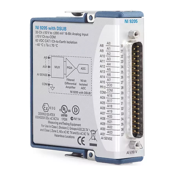
This document describes how to use the National Instruments 9205 and includes specifications and pin assignments for the NI 9205. In this document, the NI 9205 with spring terminal and the NI 9205 with DSUB are referred to inclusively as the NI 9205. Visit... -
Page 3: Safety Guidelines For Hazardous Voltages
Hot Surface hot. Touching this component may result in bodily injury. Safety Guidelines for Hazardous Voltages You can connect hazardous voltages only to the NI 9205 with spring terminal. Do not connect hazardous voltages to the NI 9205 with DSUB. -
Page 4: Safety Guidelines For Hazardous Locations
Figure 1. NI 9940 Connector Backshell Safety Guidelines for Hazardous Locations The NI 9205 is suitable for use in Class I, Division 2, Groups A, B, C, D, T4 hazardous locations; Class I, Zone 2, AEx nC IIC T4 and NI 9205 Operating Instructions and Specifications ni.com... - Page 5 Ex nC IIC T4 hazardous locations; and nonhazardous locations only. Follow these guidelines if you are installing the NI 9205 in a potentially explosive environment. Not following these guidelines may result in serious injury or death. Do not disconnect I/O-side wires or connectors...
- Page 6 II 3G and is suitable for use in Zone 2 hazardous locations. If you are using the NI 9205 in Gas Group IIC hazardous locations or in ambient temperatures of –40 °C ≤ Ta ≤ 70 °C, you must use the device in an NI chassis that has been evaluated as EEx nC IIC T4, Ex nA IIC T4, or Ex nL IIC T4 equipment.
-
Page 7: Connecting The Ni 9205
Connecting the NI 9205 The NI 9205 is a 32-channel single-ended/16-channel differential analog input module. AI10 AI11 AI10 AI12 AI11 AI13 AI12 AI13 AI14 AI14 AI15 AI15 AI24 AI16 PFIO AI17 AI25 AI16 AI18 AI26 AI24 AI17 AI25 AI19 AI27... - Page 8 37-pin DSUB connector. Each analog input channel has an AI terminal or pin to which you can connect an analog output device. The NI 9205 is capable of an aggregate sampling rate of 250 kS/s. The NI 9205 also supports triggering. Refer to the software help for information about input trigger modes.
-
Page 9: Connecting Wires To The Ni 9205 Spring-Terminal Connector
Filtered Differential Amplifier NI 9205 Figure 3. Input Circuitry for One Analog Channel on the NI 9205 Connecting Wires to the NI 9205 Spring-Terminal Connector Use a flathead screwdriver with a blade smaller than 2.3 × 1.0 mm (0.09 × 0.04 in.) to connect wires to the detachable spring-terminal connector. -
Page 10: Wiring For High-Vibration Applications
For the NI 9205 with spring terminal, use the NI 9940 backshell to protect the connections. For the NI 9205 with DSUB, use a 37-pin shielded cable or the NI 9933 backshell to protect the connections. -
Page 11: Connecting Devices To The Ni 9205
Figure 5. NI 9933 Connector Backshell Connecting Devices to the NI 9205 You can connect the NI 9205 directly to a variety of devices and other signal sources. Make sure the devices you connect to the NI 9205 are compatible with the input specifications of the module. -
Page 12: Differential Measurements
NI 9205 to 16. Table 1 shows the signal pairs that are valid for differential connection configurations with the NI 9205. Table 1. Differential Pairs... - Page 13 This signal name indicates the differential pair. Refer to Table1 for a list of differential signal pairs. Figure 6. Connecting a Device to the NI 9205 Using Differential Connections In a differential connection configuration, the NI 9205 rejects the common-mode noise voltage, V , during the measurement of V ©...
-
Page 14: Referenced Single-Ended (Rse) Measurements
NI 9205 using RSE connections. PGIA NI 9205 Figure 7. Connecting a Device to the NI 9205 Using RSE Connections In an RSE connection configuration, the NI 9205 measures each input channel with respect to COM. NI 9205 Operating Instructions and Specifications... -
Page 15: Non-Referenced, Single-Ended (Nrse) Measurements
The behavior of this configuration is similar to the behavior of RSE connections, but it provides improved noise rejection. Refer to Figure 8 for an illustration of connecting a device to the NI 9205 using NRSE connections. © National Instruments Corp. -
Page 16: Sleep Mode
PGIA AISENSE NI 9205 Figure 8. Connecting a Device to the NI 9205 Using NRSE Connections In an NRSE connection configuration, the NI 9205 measures each input channel with respect to AI SENSE. Sleep Mode This module supports a low-power sleep mode. Support for sleep mode at the system level depends on the chassis that the module is plugged into. -
Page 17: Analog Input Characteristics
Number of channels......32 single-ended or 16 differential analog input channels, 1 digital input channel, and 1 digital output channel ADC resolution......... 16 bits DNL ..........No missing codes guaranteed © National Instruments Corp. NI 9205 Operating Instructions and Specifications... - Page 18 Nominal input ranges......±10 V, ±5 V, ±1 V, ±0.2 V Minimum overrange (for 10 V range) ........ 4% Maximum working voltage for analog inputs (signal + common mode) ....Each channel must remain within ±10.4 V of common NI 9205 Operating Instructions and Specifications ni.com...
- Page 19 Non-adjacent channels ....–70 dB Analog bandwidth......370 kHz Overvoltage protection AI channel (0 to 31) ....±30 V (one channel only) AISENSE ........±30 V CMRR (DC to 60 Hz)....... 100 dB © National Instruments Corp. NI 9205 Operating Instructions and Specifications...
- Page 20 100 k Frequency (Hz) Settling time for multichannel measurements, accuracy, all ranges ±120 ppm of full-scale step (±8 LSB)........4 μs convert interval ±30 ppm of full-scale step (±2 LSB)........8 μs convert interval NI 9205 Operating Instructions and Specifications ni.com...
- Page 21 Resolution........10 bits, 1 in 1,024 Bandwidth (–3 dB) ..... 370 kHz Accuracy........±1% of full scale Scaling coefficients Typical Scaling Nominal Range (V) Coefficient (μV/LSB) ±10 ±5 164.2 ±1 32.8 ±0.2 6.57 © National Instruments Corp. NI 9205 Operating Instructions and Specifications...
- Page 22 100 samples immediately following internal calibration. Refer to the Absolute accuracy formulas for more information. † Sensitivity is the smallest voltage change that can be detected. It is a function of noise. NI 9205 Operating Instructions and Specifications ni.com...
- Page 23 Offset Gain Offset Nominal Error Error Error Gain Tempco Range Reference (ppm of (ppm of (ppm of Tempco (ppm of Reading) (ppm/°C) Tempco Range) Range/°C) Range) ±10 ±5 ±1 ±0.2 © National Instruments Corp. NI 9205 Operating Instructions and Specifications...
- Page 24 NoiseUncertainty = (240 μV · 3) / Noise Uncertainty = 72 μV AbsoluteAccuracy = 10 V · 476 ppm + 10 V · 140 ppm + 72 μV AbsoluteAccuracy = 6,232 μV (rounds to 6,230 μV) NI 9205 Operating Instructions and Specifications ni.com...
-
Page 25: Digital Characteristics
), sourcing 75 μA Output high voltage (V 2.1 V 3.3 V ), sinking 250 μA Output low voltage (V 0.4 V External digital triggers Source......... PFI0 Delay .......... 100 ns max © National Instruments Corp. NI 9205 Operating Instructions and Specifications... -
Page 26: Power Requirements
Spring-terminal wiring...... 18 to 28 AWG copper conductor wire with 7 mm (0.28 in.) of insulation stripped from the end Weight NI 9205 with spring terminal ..158 g (5.8 oz) NI 9205 with DSUB....148 g (5.3 oz) NI 9205 Operating Instructions and Specifications ni.com... -
Page 27: Maximum Voltage
Safety Maximum Voltage Connect only voltages that are within the following limits. AI, PFI0, and DO-to-COM....±30 VDC NI 9205 with Spring Terminal Isolation Voltages Channel-to-channel......None Channel-to-earth ground Continuous ......... 250 V , Measurement Category II Withstand........2,300 V... - Page 28 Do not connect the NI 9205 with spring terminal Caution to signals or use for measurements within Measurement Categories III or IV. NI 9205 with DSUB Isolation Voltages Channel-to-channel......None Channel-to-earth ground Continuous ......... 60 VDC, Measurement Category I Withstand........1,000 V...
- Page 29 Do not connect the NI 9205 with DSUB to Caution signals or use for measurements within Measurement Categories II, III, or IV. Safety Standards This product is designed to meet the requirements of the following standards of safety for electrical equipment for measurement, control, and laboratory use: •...
- Page 30 Europe (DEMKO)......EEx nC IIC T4 Environmental National Instruments C Series modules are intended for indoor use only but may be used outdoors if installed in a suitable enclosure. Refer to the manual for the chassis you are using for more information about meeting these specifications.
-
Page 31: Shock And Vibration
To meet these specifications, you must panel mount the system and use a backshell kit or shielded cable to protect the connections. Use the NI 9940 backshell for the NI 9205 with spring terminal and a 37-pin shielded cable or the NI 9933 backshell for the NI 9205 with DSUB. -
Page 32: Electromagnetic Compatibility
2006/95/EC; Low-Voltage Directive (safety) • 2004/108/EC; Electromagnetic Compatibility Directive (EMC) Refer to the Declaration of Conformity (DoC) for Note this product for any additional regulatory compliance information. To obtain the DoC for this product, visit NI 9205 Operating Instructions and Specifications ni.com... -
Page 33: Environmental Management
Certification column. Environmental Management National Instruments is committed to designing and manufacturing products in an environmentally responsible manner. NI recognizes that eliminating certain hazardous substances from our products is beneficial not only to the environment but also to NI customers. -
Page 34: Where To Go For Support
NI 9205 at ni.com/calibration Calibration interval ......2 years Where to Go for Support The National Instruments Web site is your complete resource for technical support. At you have access to ni.com/support everything from troubleshooting and application development self-help resources to email and phone assistance from NI Application Engineers. - Page 35 National Instruments also has offices located around the world to help address your support needs. For telephone support in the United States, create your service request at ni.com/support and follow the calling instructions or dial 512 795 8248. For telephone support outside the United States, contact your local...
- Page 36 National Instruments, NI, ni.com, and LabVIEW are trademarks of National Instruments Corporation. Refer to the Terms of Use section on ni.com/legal for more information about National Instruments trademarks. Other product and company names mentioned herein are trademarks or trade names of their respective companies.
Need help?
Do you have a question about the NI 9205 and is the answer not in the manual?
Questions and answers