National Instruments NI 9205 Getting Started Manual
16 ai differential/32 ai single-ended, ±200 mv to ±10 v, 16 bit, 250 ks/s aggregate
Hide thumbs
Also See for NI 9205:
- Operating instructions manual (37 pages) ,
- Getting started manual (27 pages)

Related Manuals for National Instruments NI 9205


Summary of Contents for National Instruments NI 9205
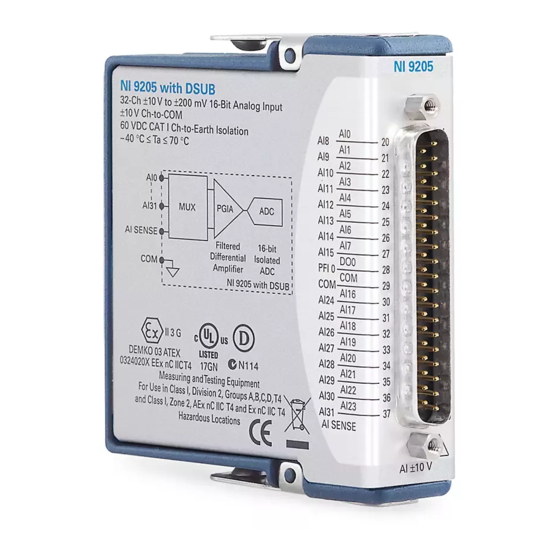
- Page 1 GETTING STARTED GUIDE NI 9205 16 AI Differential/32 AI Single-Ended, ±200 mV to ±10 V, 16 Bit, 250 kS/s Aggregate...
-
Page 2: Safety Guidelines
This document explains how to connect to the NI 9205. In this document, the NI 9205 with spring terminal and the NI 9205 with DSUB are referred to inclusively as the NI 9205. Before you begin, complete the software and... -
Page 3: Safety Voltages
Connect only voltages that are within the following limits: Maximum voltage Channel-to-COM ±30 V DC The maximum voltage that can be applied or output between AI and COM without creating a safety hazard. NI 9205 Getting Started Guide | © National Instruments | 3... -
Page 4: Ni 9205 With Spring Terminal Isolation Voltages
U.S. or 230 V for Europe. Do not connect the NI 9205 with spring Caution terminal to signals or use for measurements within Measurement Categories III or IV. NI 9205 with DSUB Isolation Voltages Channel-to-channel None 4 | ni.com | NI 9205 Getting Started Guide... - Page 5 Do not connect the NI 9205 with DSUB to Caution signals or use for measurements within Measurement Categories II, III, or IV. NI 9205 Getting Started Guide | © National Instruments | 5...
-
Page 6: Safety Guidelines For Hazardous Voltages
Safety Guidelines for Hazardous Voltages You can connect hazardous voltages only to the NI 9205 with spring terminal . Do not connect hazardous voltages to the NI 9205 with DSUB. If hazardous voltages are connected to the device, take the following precautions. -
Page 7: Safety Guidelines For Hazardous Locations
Safety Guidelines for Hazardous Locations The NI 9205 is suitable for use in Class I, Division 2, Groups A, B, C, D, T4 hazardous locations; Class I, Zone 2, AEx nA IIC T4 Gc and Ex nA IIC T4 Gc hazardous locations; and nonhazardous locations only. -
Page 8: Special Conditions For Hazardous Locations Use In Europe And Internationally
II 3G and is suitable for use in Zone 2 hazardous locations, in ambient temperatures of -40 °C ≤ Ta ≤ 70 °C. If you are using the NI 9205 in Gas Group IIC hazardous locations, you must use the device in an NI chassis that has been evaluated as Ex nC IIC T4, Ex IIC T4, Ex nA IIC T4, or Ex nL IIC T4 equipment. -
Page 9: Electromagnetic Compatibility Guidelines
This product is intended for use in industrial locations. However, harmful interference may occur in some installations, when the product is connected to a peripheral device or test object, or if the NI 9205 Getting Started Guide | © National Instruments | 9... - Page 10 To ensure the specified EMC performance of Caution the NI 9205 with DSUB, the length of all I/O cables must be no longer than 30 m (100 ft). To ensure the specified EMC performance,...
-
Page 11: Special Conditions For Marine Applications
In addition, take precautions when designing, selecting, and installing measurement probes and cables to ensure that the desired EMC performance is attained. NI 9205 Getting Started Guide | © National Instruments | 11... -
Page 12: Preparing The Environment
Preparing the Environment Ensure that the environment in which you are using the NI 9205 meets the following specifications. Operating temperature -40 °C to 70 °C (IEC 60068-2-1, IEC 60068-2-2) Operating humidity 10% RH to 90% RH, (IEC 60068-2-78) noncondensing... - Page 13 AI18 AI24 AI17 AI25 AI27 AI19 AI18 AI26 AI28 AI20 AI19 AI27 AI20 AI29 AI21 AI28 AI21 AI30 AI22 AI29 AI22 AI31 AI30 AI23 AI23 AI31 AISENSE AISENSE PFI0 NI 9205 Getting Started Guide | © National Instruments | 13...
- Page 14 Signals You can connect single-ended or differential signals to the NI 9205. Use a differential measurement configuration to attain more accurate measurements and less noise. The following table shows the signal pairs that are valid for differential connection configurations with the NI 9205.
- Page 15 Table 2. Differential Pairs Channel AI + AI10 AI11 AI12 AI13 AI14 AI15 AI16 AI24 AI17 AI25 AI18 AI26 NI 9205 Getting Started Guide | © National Instruments | 15...
- Page 16 Table 2. Differential Pairs (Continued) Channel AI + AI19 AI27 AI20 AI28 AI21 AI29 AI22 AI30 AI23 AI31 16 | ni.com | NI 9205 Getting Started Guide...
-
Page 17: Connecting Grounded Differential Signals
In a differential configuration, the NI 9205 rejects the common- mode noise voltage during the measurement of V . To connect grounded differential signals to the NI 9205, you must also connect the signal reference to COM. NI 9205 Getting Started Guide | © National Instruments | 17... -
Page 18: Connecting Floating Differential Signals
– AI9 (CH1–) NI 9205 To connect floating differential signals to the NI 9205, you must connect the negative signal to COM through a 1 MΩ resistor to keep the voltage within the maximum working voltage. If the voltage source is outside the maximum working voltage, the NI 9205 does not read data accurately. -
Page 19: Connecting Rse Voltage Signals
NI 9205 In an RSE configuration, the NI 9205 measures each channel with respect to COM. To connect RSE signals to the NI 9205, you must connect the voltage ground signal to COM to keep the maximum working voltage in the specified range. -
Page 20: Connecting Nrse Voltage Signals
10 V of COM. Connecting NRSE Voltage Signals You can connect non-referenced single-ended (NRSE) signals to the NI 9205. Figure 4. Connecting an RSE Voltage Signal to the NI 9205 – PGIA – AISENSE NI 9205 20 | ni.com | NI 9205 Getting Started Guide... -
Page 21: Ni 9205 Connection Guidelines
NI 9205 with spring terminal. • For the NI 9205 with spring terminal, push the wire into the terminal when using a solid wire or a stranded wire with a ferrule. -
Page 22: High-Vibration Application Connections
If your application is subject to high vibration, NI recommends that you use the NI 9940 backshell kit to protect connections to the NI 9205 with spring terminal. Overvoltage Protection The NI 9205 provides overvoltage protection for each channel. Refer to the device datasheet on ni.com/manuals Note for more information about overvoltage protection. -
Page 23: Where To Go Next
NI 9205 Datasheet NI-RIO Help NI-DAQmx Help LabVIEW FPGA Help LabVIEW Help RELATED INFORMATION C Series Documentation Services ni.com/services & Resources ni.com/info cseriesdoc Located at ni.com/manuals Installs with the software NI 9205 Getting Started Guide | © National Instruments | 23... -
Page 24: Worldwide Support And Services
(EMC) and product safety. You can obtain the DoC for your product by visiting ni.com/certification. If your product supports calibration, you can obtain the calibration certificate for your product at ni.com/calibration. 24 | ni.com | NI 9205 Getting Started Guide... - Page 25 United States, visit the Worldwide Offices section of ni.com/niglobal to access the branch office websites, which provide up-to-date contact information, support phone numbers, email addresses, and current events. NI 9205 Getting Started Guide | © National Instruments | 25...
- Page 26 For patents covering NI products/technology, refer to the appropriate location: Help»Patents in your software, file on your media, or the National Instruments Patent Notice at patents.txt ni.com/ . You can find information about end-user license agreements (EULAs) and third-party patents legal notices in the readme file for your NI product.
Need help?
Do you have a question about the NI 9205 and is the answer not in the manual?
Questions and answers