
Related Manuals for Yamaha XY-X series


Summary of Contents for Yamaha XY-X series
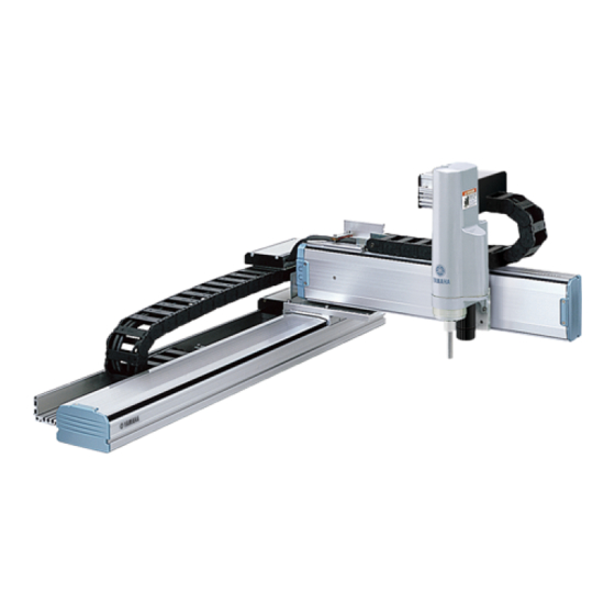
- Page 1 XY-X series YAMAHA CARTESIAN ROBOT User’s Manual ENGLISH YAMAHA MOTOR CO., LTD. IM Operations 882 Soude, Naka-ku, Hamamatsu, Shizuoka 435-0054.Japan E40-Ver. 1.02 URL http://www.yamaha-motor.jp/robot/index.html...
-
Page 3: Table Of Contents
General Contents Chapter 1 USING THE ROBOT SAFELY Safety Information Essential Caution Items Special Training for Industrial Robot Operation Robot Safety Functions Safety Measures for the System 1-10 Trial Run 1-10 Work Within the Safeguard Enclosure 1-11 Automatic Operation 1-11 Adjustment and Inspection 1-12 Repair and Modification... - Page 4 Chapter 4 INSTALLING THE TOOL Single arm type, double arm type, 2-axis model ZFH (single arm type, double arm type) ZFL (single arm type, double arm type) Chapter 5 USER WIRING AND USER PIPING Cable carrier type Wiring/piping to the single arm robot Wiring/piping to the double arm robot Cable carrier specifications Chapter 6 PERIODIC INSPECTIONS...
- Page 5 Chapter 1 USING THE ROBOT SAFELY Contents Safety Information Essential Caution Items Special Training for Industrial Robot Operation 1-8 Robot Safety Functions Safety Measures for the System 1-10 Trial Run 1-10 Work Within the Safeguard Enclosure 1-11 Automatic Operation 1-11 Adjustment and Inspection 1-12 10.
-
Page 7: Safety Information
Chapter Industrial robots are highly programmable machines that provide a large degree of freedom in movement. To ensure correct and safe use of YAMAHA robots, carefully read this manual to make yourself well acquainted with the contents. FOLLOW THE WARNINGS, CAUTIONS AND INSTRUCTIONS INCLUDED IN THIS MANUAL. Failure... -
Page 8: Essential Caution Items
2. Essential Caution Items 2. Essential Caution Items Chapter Particularly important cautions for handling or operating the robot are described below. In addition, safety information about installation, operation, inspection and maintenance is provided in each chapter. Be sure to comply with these instructions to ensure safe use of the robot. - Page 9 2. Essential Caution Items Warning label 2 is affixed to the robot. Use caution to prevent hands or fingers from being pinched or crushed in the robot’s moving parts during transporting the robot or teaching, etc. Chapter WARNING Moving parts can pinch or crush.
- Page 10 2. Essential Caution Items (5) Do not use the robot in locations possible subject to electromagnetic interference, etc. WARNING Chapter AVOID USING THE ROBOT IN LOCATIONS SUBJECT TO ELECTROMAGNETIC INTERFERENCE, ELECTROSTATIC DISCHARGE OR RADIO FREQUENCY INTERFERENCE. MALFUNCTIONS MIGHT OTHERWISE OCCUR. (6) Use caution when releasing the brake for the Z-axis (vertical axis).
- Page 11 WHEN DISASSEMBLING OR ASSEMBLING THE MOTOR FOR A BALL-SCREW DRIVE TYPE ROBOT, A STRONG MAGNETIC ATTRACTION FORCE WILL BE PRESENT BETWEEN THE MOTOR STATOR (FIXED COIL) AND ROTOR (ROTATING MAGNET), CAUSING A RISK OF PINCHING HANDS, ETC. A YAMAHA-TRAINED OPERATOR MUST CARRY OUT THIS WORK USING THE YAMAHA-RECOMMENDED JIGS. (13)
- Page 12 • REFER TO THE "YAMAHA ROBOT CONTROLLER USER'S MANUAL" FOR PRECAUTIONS ON HANDLING THE CONTROLLER. NEVER TOUCH ANY INTERNAL PARTS OF THE CONTROLLER. (15) Consult YAMAHA for corrective action when the robot is damaged or malfunctions occur. WARNING IF ANY PART OF THE ROBOT IS DAMAGED OR ANY MALFUNCTION OCCURS, CONTINUING THE OPERATION MAY BE VERY DANGEROUS.
- Page 13 2. Essential Caution Items (18) Do not remove, alter or stain the warning labels WARNING Chapter IF THE WARNING LABELS ARE REMOVED OR DIFFICULT TO SEE, THEN ESSENTIAL PRECAUTIONS MIGHT NOT BE TAKEN RESULTING IN ACCIDENTS. • DO NOT REMOVE, ALTER OR STAIN THE WARNING LABELS ON THE ROBOT. •...
-
Page 14: Special Training For Industrial Robot Operation
Since YAMAHA Cartesian robot XY series falls under the industrial robot category, the user must observe local regulations and safety standards... -
Page 15: Robot Safety Functions
4. Robot Safety Functions 4. Robot Safety Functions Chapter (1) Overload detection This function detects an overload applied to the motor and shuts off the servo power. (2) Overheat detection This detects an abnormal rise in the controller driver temperature and shuts off the servo power. -
Page 16: Safety Measures For The System
5. Safety Measures for the System 5. Safety Measures for the System Chapter When the robot is commonly used in conjunction with an automated system, dangerous situations are more likely to occur from the automated system than from the robot itself. Appropriate safety measures must be taken on the part of the system manufacturer according to the individual system. -
Page 17: Work Within The Safeguard Enclosure
7. Work Within the Safeguard Enclosure 7. Work Within the Safeguard Enclosure Chapter When work is required in the safeguard enclosure, always turn the controller power OFF and place a sign indicating that the robot is being adjusted or serviced in order to keep any other personnel from touching the controller power switch or operation panel, except for the time during soft limit setting and teaching operation. -
Page 18: Adjustment And Inspection
9. Adjustment and Inspection 9. Adjustment and Inspection Chapter WARNING DO NOT ATTEMPT ANY INSTALLATION, ADJUSTMENT, INSPECTION OR MAINTENANCE UNLESS DESCRIBED IN THIS MANUAL. UNEXPECTED ACCIDENTS OR TROUBLES MAY OTHERWISE RESULT. 10. Repair and Modification WARNING DO NOT ATTEMPT ANY REPAIR, PART REPLACEMENT OR MODIFICATION UNLESS DESCRIBED IN THIS MANUAL. -
Page 19: Warranty
If a failure or breakdown occurs due to defects in materials or workmanship in the genuine parts constituting this YAMAHA robot and/or related product within the warranty period, then YAMAHA will repair or replace those parts free of charge (hereafter called "warranty repair"). -
Page 20: Ce Marking
12. CE Marking 12. CE Marking Chapter Refer to the following YAMAHA robot controller user's manuals for details on the related CE Marking for export to or use in EU regions. • CE marking supplement manual for RCX series 1-14... - Page 21 Chapter 2 INSTALLATION Contents Installation bolt types Installation bolt nominal length Tightening torque Installation methods...
-
Page 23: Installation Bolt Types
1. Installation bolt types WARNING Always turn the controller power OFF before installing the robot. Serious accidents might occur if the robot starts to operate during installation. The NXY is installed with one of the following two methods. Chapter Method A : Open through holes on the installation base and install with M6 bolts from below. -
Page 24: Tightening Torque
1) Open a φ 6.5 through hole on the installation base's robot installation surface. For machining positions, refer to the external view and dimensions in the catalog or website (www.yamaha-motor.co.jp/global/industrial/robot). 2) Set the robot on the installation base and fix with M6 bolts from below. - Page 25 1) Tap M6 coarse screw thread holes into the installation base where the robot is to be installed. For machining positions, refer to the external view and dimensions in the catalog or website (www.yamaha-motor.co.jp/global/industrial/robot). Chapter 2) Remove the end cover 1 (upper end cover) from each end of the robot. Then remove the screws (4 pcs) holding the top cover and remove the top cover.
- Page 26 MEMO...
- Page 27 Chapter 3 PROTECTIVE CONNECTIONS Contents Ground terminal Ground wire Wiring methods Grounding to the single arm robot Grounding to the double arm robot...
-
Page 29: Ground Terminal
1. Ground terminal Connect the robot side ground terminal with the external protective conductor's ground terminal using a ground wire. WARNING • ALWAYS GROUND THE ROBOT AND CONTROLLER TO PREVENT ELECTRICAL SHOCKS. • ALWAYS TURN THE CONTROLLER POWER OFF BEFORE CONNECTING THE GROUND TO PREVENT ELECTRICAL SHOCKS. -
Page 30: Ground Wire
2. Ground wire 2. Ground wire Use an AWG14 (2.0mm ) or larger ground wire with a total length of 1m or less. Crimp an M4 ring-tongue terminal on the end of the wire connected to the robot. 3. Wiring methods Chapter An M4 small screw with spring washer and lock washer are attached to the ground terminal. -
Page 31: Grounding To The Double Arm Robot
3. Wiring methods Grounding to the double arm robot 1) Remove the M4 bolts (2 pcs) on the top of the X-wiring box, and open the cover by sliding toward the robot. Chapter 2) Connect the ground wire to the ground terminal attached in the X-axis wiring box. Ground terminal Ground wire... - Page 32 MEMO...
- Page 33 Chapter 4 INSTALLING THE TOOL Contents Single arm type, double arm type, 2-axis model 4-1 ZFH (single arm type, double arm type) ZFL (single arm type, double arm type)
-
Page 35: Single Arm Type, Double Arm Type, 2-Axis Model
1. Single arm type, double arm type, 2-axis model WARNING • ALWAYS TURN THE CONTROLLER POWER OFF BEFORE INSTALLING A TOOL TO PREVENT AN ACCIDENT. • BEFORE INSTALLING A TOOL, CHECK THAT THE ROBOT IS SECURELY FIXED TO THE BASE. •... -
Page 36: Zfh (Single Arm Type, Double Arm Type)
2. ZFH (single arm type, double arm type) 2. ZFH (single arm type, double arm type) When using the 3rd-axis model with ZFH for the 3rd-axis, install the workpiece onto the ZFH slider by using four M5 coarse thread tap holes and a φ 5 reamer hole opened on the slider's workpiece installation surface. -
Page 37: Zfl (Single Arm Type, Double Arm Type)
3. ZFL (single arm type, double arm type) 3. ZFL (single arm type, double arm type) When using the 3rd-axis model with ZFL for the 3rd-axis, install the workpiece onto the ZFL slider by using six M5 coarse thread tap holes and a φ 5 reamer hole opened on the slider's workpiece installation surface. - Page 38 MEMO...
- Page 39 Chapter 5 USER WIRING AND USER PIPING Contents Cable carrier type Wiring/piping to the single arm robot Wiring/piping to the double arm robot Cable carrier specifications...
-
Page 41: Cable Carrier Type
1. Cable carrier type WARNING ALWAYS TURN OFF THE CONTROLLER BEFORE WIRING AND PIPING TO PREVENT ELECTRICAL SHOCKS. 1. Cable carrier type A cable carrier is mounted as a standard between the X and Y axes. When 3rd-axis are used, a cable carrier is also provided between the Y and Z axes, and when using 4th-axis, a cable carrier is also provided between the Z and R axes. - Page 42 1. Cable carrier type 2) Set the outer lids back in the original position after finishing the wiring layout. Chapter 3) Fix the wiring materials with Insulock ties as necessary (Insulock base must be attached). See the photograph below for the machining position.
-
Page 43: Wiring/Piping To The Double Arm Robot
1. Cable carrier type Chapter Wiring/piping to the double arm robot CAUTION Wiring layout must be designed in the unoccupied area. 1) Remove the outer lids on the cable carrier by using a flat-tip screwdriver. The outer lids do not have to be removed if the connectors are not attached to the wiring materials. - Page 44 1. Cable carrier type 2) Set the outer lids back in the original position after finishing the wiring layout. Chapter 3) Fix the wiring materials with Insulock ties as necessary (Insulock base must be attached). See the photograph below for the machining position.
- Page 45 1. Cable carrier type 4) A bundle of wires can be set either left or right of the robot. Chapter...
-
Page 46: Cable Carrier Specifications
• When setting the harness and air tube into the cable carrier, make sure that the total cross-sectional area of all wires and pipes, including the YAMAHA cable, inside the cable carrier does not exceed 30% of the cable carrier’s cross-... - Page 47 Chapter 6 PERIODIC INSPECTIONS Contents Before beginning work Periodic inspection Daily inspection Three-month inspection Six-month inspection Three-year inspection Replenishing grease to the linear guide Replenishing grease to the ball screw...
-
Page 49: Before Beginning Work
1. Before beginning work Periodic inspection and maintenance are essential to ensure safe and efficient operation of YAMAHA robots. This chapter describes periodic inspection items and procedures for the NXY. Before beginning work, read the precautions below and also in Chapter 1 "Using the Robot Safely"... - Page 50 1. Before beginning work When applying grease to the ball screw and linear guide, take the following precautions. WARNING PRECAUTIONS WHEN HANDLING GREASE: • INFLAMMATION MAY OCCUR IF THIS GETS IN THE EYES. BEFORE HANDLING THE GREASE, WEAR YOUR SAFETY GOGGLES TO ENSURE THE GREASE WILL NOT COME IN CONTACT WITH THE EYES.
-
Page 51: Periodic Inspection
Standard robots: Albania No. 2 (Shell) Daphne Eponex No. 2 (Idemitsu) Clean room robots: LG-2 (NSK) CAUTION Using grease other than those recommended by YAMAHA might shorten the service life of the ball screw, linear guide and linear bushing shaft. -
Page 52: Six-Month Inspection
6 months. CAUTION Using grease other than those recommended by YAMAHA might shorten the service life of the ball screw and linear guide. Three-year inspection Check the following points every 3 years or more often if the robot is used frequently. -
Page 53: Replenishing Grease To The Linear Guide
Daphne Eponex No. 2 (Idemitsu) CAUTION When designated by YAMAHA and the user, special grease, such as splatter- proof grease, may be applied when the robot is delivered. In this case, apply the appropriate grease as indicated in the delivery specifi cation drawings, etc. -
Page 54: Replenishing Grease To The Ball Screw
Daphne Eponex No. 2 (Idemitsu) CAUTION • When designated by YAMAHA and the user, special grease, such as splatter- proof grease, may be applied when the robot is delivered. In this case, apply the appropriate grease as indicated in the delivery specifi cation drawings, etc. - Page 55 4. Replenishing grease to the ball screw 1) Use the recommended grease nipple, A-M6X1(JIS B1575). 2) Turn the controller power OFF. When the ZF unit is attached for the 3rd-axis, the replenishment work can be carried out easier by moving the Z-axis slider to near the motor (near the origin) and turning the controller power OFF.
- Page 56 All rights reserved. No part of this publication may be reproduced in any form without the permission of YAMAHA MOTOR CO., LTD. Information furnished by YAMAHA in this manual is believed to be reliable. However, no responsibility is assumed for possible inaccuracies or omissions.
Need help?
Do you have a question about the XY-X series and is the answer not in the manual?
Questions and answers