Table of Contents
Advertisement
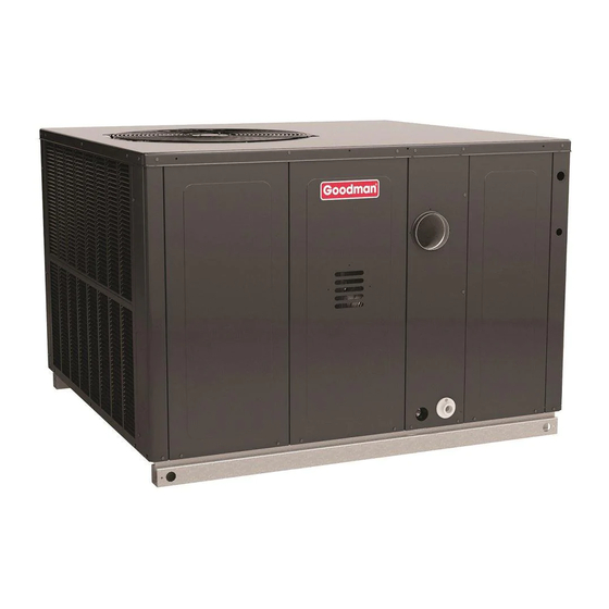
GPG16 M SERIES
S
P
InGlE
ackaGEd
5 t
on
I
I
nStallatIon
nStRUctIonS
This forced air central unit design complies with
requirements embodied in The American National Standard
/ National Standard of Canada ANSI Z21.47•CSA-2.3 Gas-
fired central furnaces.
Only personnel that have been trained to install, adjust, service or
repair(hereinafter, "service") the equipment specified in this manual
should service the equipment. The manufacturer will not be responsible
for any injury or property damage arising from improper service or service
procedures. If you service this unit, you assume responsibility for any
injury or property damage which may result. In addition, in jurisdictions
that require one or more licenses to service the equipment specified in
this manual, only licensed personnel should servise the equipment.
Improper installation, adjustment, servicing or repair of the equipment
specified in this manual, or attempting to install, adjust, service or repair
the equipment specified in this manual without proper training may result
in product damage, property damage, personal injury or death.
Our continuing commitment to quality products may mean a change in specifications without notice.
IOG-3017E
01/20
G
/E
aS
lEctRIc
WARNING
©2016-2020 Goodman Company, L.P.
19001 Kermier Rd., Waller, TX 77484
www.goodmanmfg.com
H
& c
EatInG
oolInG
c
.......................................................................6
R
c
P
oof
URb
R
t
d
oof
oP
Uct
R
d
IGGInG
W
c
EIGHtS
and
E
lEctRIcal
c
a
IRcUlatInG
IR
c
d
ondEnSatE
S
, a
taRtUP
djUStMEntS
a
a
IR
floW
djUStMEntS
G
S
c
n
S
oRMal
EqUEncE
M
...................................................................21
aIntEnancE
t
RoUblESHootInG
a
a b
PPEndIx
a
b E
PPEndIx
lEctRIcal
a
c U
PPEndIx
a
d M
PPEndIx
W
d
IRInG
IaGRaM
S
c
taRtUP
HEcklISt
FOR CALIFORNIA CONSUMERS
U
nIt
INDEX
.........................................................2
........................................................2
......................................................3
-I
oSt
nStallatIon
cHEckS
c
..........................................6
onnEctIonS
.................................................................7
G
....................................7
EntER
of
RavIty
............................................................8
............................................................10
...........................................12
f
.........................................13
and
IltERS
c
....................................13
RaIn
onnEctIon
,
............................14
and
...................................................15
.........................................................15
o
o
.................................19
f
..........................................................23
P
t
loWER
ERfoRMancE
........................................26
.........................................27
nIt
dIMEnSIonS
-M
a
.......................................28
In
ax
IRfloW
............................................................29
..........................................................30
PROP 65 WARNING
WARNING
Cancer and Reproductive Harm -
www.P65Warnings.ca.gov
..........................6
.................25
ablES
0140M00517-A
Advertisement
Table of Contents

Related Manuals for Goodman GPG16 M Series


Summary of Contents for Goodman GPG16 M Series
-
Page 1: Table Of Contents
GPG16 M SERIES & c InGlE ackaGEd lEctRIc EatInG oolInG nStallatIon nStRUctIonS INDEX ............2 EPlacEMEnt aRtS ............2 afEty nStRUctIonS ............3 EnERal InfoRMatIon ...............6 lEaRancES ......6 nStallatIon cHEckS ..........6 onnEctIonS ..............7 IGGInG EtaIlS ........7 EIGHtS EntER RavIty ............8 lEctRIcal WIRInG ............10... -
Page 2: Replacement Parts
WARNING CONSUMER AFFAIRS GOODMAN MANUFACTURING COMPANY, L.P. HoUld ovERHEatInG occUR oR tHE GaS SUPPly faIl 7401 SECURITY WAY to SHUt off tHURn off tHE ManUal GaS SHUtoff HOUSTON, TEXAS 77040... -
Page 3: General Information
Rated performance is delivered at the specified airflow. See product specification sheet for residential packaged models. Specification sheets can be found at www.goodmanmfg.com for Goodman brand products. Within the website, please select the products menu and then select the submenu for the type of product to be... - Page 4 Obtain from: nStallatIon HEckS American National Standards Institute Carefully read all instructions for the installation prior www.ansi.org to installing unit. Ensure each step or procedure is understood and any special considerations are taken into System design and installation should also, where account before starting installation.
- Page 5 • The unit shall not be connected to a chimney flue REcaUtIonS serving a separate appliance designed to burn solid • Do not stand or walk on the unit. fuel. • Do not drill holes anywhere in panels or in the base •...
-
Page 6: Learances
CAUTION ll cURbS look SIMIlaR o avoId IncoRREct cURb PoSItIonInG cHEck job PlanS caREfUlly and vERIfy MaRkInGS on cURb aSSEMbly nStRUctIonS May vaRy In cURb StylES and SUPERSEdES InfoRMatIon SHoWn See the manual shipped with the roof curb for assembly and installation instructions. - Page 7 • Two spreader bars must span over the unit to prevent damage to the cabinet by the lift cables. Spreader bars must be of sufficient length so that cables do not come in contact with the unit during transport. Remove wood struts mounted beneath unit base frame before setting unit on roof curb.
-
Page 8: Etails
Note: Unit should be lifted at a point above center of gravity. CAUTION Corner Weights (lb) Shipping Operating o PREvEnt daMaGE to tHE WIRInG PRotEct WIRInG Model X (in) Y (in) Weight (lb) Weight (lb) fRoM SHaRP EdGES folloW natIonal ElEctRIcal GPG1660140M41 183 35.8 27.5 codE and all local codES and oRdInancES... - Page 9 notE dEPEndInG on tHE oPtIonS InStallEd CAUTION locatIon of tHE coMPonEntS May vaRy In SoME ModElS o PREvEnt IMPRoPER and danGERoUS oPERatIon dUE to WIRInG ERRoRS labEl all WIRES PRIoR to WARNING dISconnEctIon WHEn SERvIcInG contRolS ERIfy PRoPER oPERatIon aftER SERvIcInG aIlURE of UnIt dUE to oPERatIon on IMPRoPER lInE voltaGE oR WItH ExcESSIvE PHaSE UnbalancE notE: a...
-
Page 10: Wiring
GAS SUPPLY PIPING HIGH VOLTAGE ENTRANCE (REMOVE PLUG) WARNING 19-3/8 31-3/8 o PREvEnt PERSonal InjURy oR dEatH dUE to IMPRoPER InStallatIon adjUStMEnt altERatIon SERvIcE oR MaIntEnancE REfER to tHIS ManUal oR addItIonal aSSIStancE oR InfoRMatIon conSUlt a qUalIfIEd InStallER SERvIcER aGEncy oR tHE GaS SUPPlIER LOW VOLTAGE ENTRANCE... - Page 11 • Listed gas appliance connectors used in IPInG accordance with the terms of their listing IMPoRtant notE: t o avoId PoSSIblE UnSatISfactoRy that are completely in the same room as the oPERatIon oR EqUIPMEnt daMaGE dUE to UndER equipment. Always use a new listed connector. fIRInG of EqUIPMEnt do not UndERSIZE tHE natURal •...
-
Page 12: Propane Gas Installations
All propane gas equipment must conform to the safety IPInG HEckS standards of NFPA 58 - Liquefied Petroleum Gas Code. CAUTION For satisfactory operation, propane gas pressure must be within 9.7 - 10.3 inches w.c. for high fire at the manifold o PREvEnt PRoPERty daMaGE oR PERSonal InjURy dUE to fIRE with all gas appliances in operation. - Page 13 1. Route gas piping to unit so that it does not interfere CAUTION with the removal of access panels. Support and align piping to prevent strains or misalignment of the ISolatEd HIS UnIt MUSt bE fRoM tHE GaS SUPPly manifold assembly. PIPInG SyStEM by cloSInG ItS IndIvIdUal ManUal 2.
- Page 14 Install condensate drain trap as shown. Use 3/4” drain line On new installations, or if a major component has been replaced, the operation of the unit must be checked. and fittings or larger. Do not operate without trap. Check unit operation as outlined in the following oRIZontal RaIn Drainage of condensate directly onto the roof may be...
- Page 15 they rotate freely. Check for bolts and screws that may Fan speed for W1 (Low Heat) is fixed setting on TB1/T2 have jarred loose during shipment to the job site. Re- and cannot be moved. tighten if necessary. Re-tighten all electrical connections. Purple wire Y2 (High Cool) and Brown wire W2 (High Heat) IEld onnEctIonS...
- Page 16 IRInG xaMPlE...
- Page 17 & R IGNITION ELECTRODE UPPly RESSURES EGUlatoR djUStMEntS FLAME SENSOR WARNING HoUld ovERHEatInG occUR oR tHE GaS SUPPly faIl to SHUt off tURn off tHE ManUal GaS SHUtoff valvE ExtERnal to tHE UnIt bEfoRE tURnInG off tHE ElEctRIcal SUPPly WARNING flaME SEnSoR and IGnItIon ElEctRodE locatIon o avoId PRoPERty daMaGE PERSonal InjURy oR...
- Page 18 dial, use the seconds as is. This gives the seconds INLET GAS PRESSURE per cubic foot of gas being delivered to the unit. 3. INPUT=GAS HTG VALUE x 3600 / SEC. PER CUBIC NATURAL Mi n. 5.0" W.C., Ma x. 10.0" W.C. FOOT PROPANE Mi n.
- Page 19 To remove manometer from gas valve: 1. Remove manometer hose from outlet pressure boss. notE: b MUSt loWER SPEEd bE SEt to GIvE tHE 2. Turn outlet pressure tap screw in to seal pressure port coRREct aIR tEMPERatURE RISE tHRoUGH tHE UnIt aS (clockwise, 7 in-lb.
- Page 20 9. Integrated ignition control will close its normally open contacts after a delay of approximately 30 seconds. WARNING This action energizes the blower motor contactor and starts the supply fan motor. Operation of the supply o avoId PRoPERty daMaGE PERSonal InjURy fan circulates air across the heat exchanger and oR dEatH dUE to fIRE oR ExPloSIon a qUalIfIEd...
-
Page 21: As Ystem Heck
2. To simulate a mechanical call for cooling lower the Inal yStEM HEckS room cooling setpoint to a value below the current 1. Check to see if all supply and return air grilles are room temperature. The cooling is energized when the adjusted and the air distribution system is balanced room temperature is above the setpoint for cooling. - Page 22 abInEt InISH aIntEnancE CAUTION Use a fine grade automotive wax on the cabinet finish to maintain the finish’s original high luster. This is especially HEEt MEtal PaRtS ScREWS clIPS and SIMIlaR important in installations with extended periods of direct ItEMS InHEREntly HavE SHaRP EdGES and It sunlight.
-
Page 23: Peration
TROUBLESHOOTING 3. Inspect and periodically clean the vent outlet (bird screen) on the access panel. GnItIon ontRol RRoR odES The following presents probable causes of questionable notE: P unit operation. Refer to Diagnostic Indicator Chart for ERIodIc obSERvatIon of tHE flaME and a an interpretation of the signal and to this section for an loG of MEaSUREMEntS aRE REcoMMEndEd... - Page 24 • Check rollout limit (5 flaSH laME EtEctEd WItH alvE loSEd If the burner flames are not properly drawn into the heat codE) exchanger, the flame rollout protection device will open. If flame is detected with the gas valve deenergized, the Possible causes are restricted or blocked flue passages, combustion and air circulator blowers are energized.
- Page 25 APPENDIX A BLOWER PERFORMANCE TABLES 5 Ton Models: GPG1660140M41 Standard Static Drive Burners High Fire Input: 140,000 BTU/HR Horizontal Flow Down Flow External External Speed Static Speed Static SCFM SCFM Pressure Pressure (ESP), in w.c. (ESP), in w.c. 0.14 1003 606 0.14 0.16 0.17...
-
Page 26: D Ata
APPENDIX B ELECTRICAL DATA lEctRIcal Outdoor Fan Optional Electric Optional Powered Optional Electrical Compressor Indoor Fan Motor Power Supply Model Number Motor Heat Convienience Power Rating QTY RLA LRA QTY HP FLA Type HP FLA Part # KW* FLA Outlet FLA Exhaust FLA Direct 43.4/43.4 70.0/70.0... - Page 27 APPENDIX C UNIT DIMENSIONS 47-5/8" 73-3/8" "A" 74" 48-5/16" Model size DIM “A” 5 ton 43-1/2” 19-1/2 RETURN 5-5/16 11” X 25” EMBOSS DRAIN 5-7/8 THRU THRU CURB BASE LOCATION SUPPLY UTILITIES 12” X 17” 7-3/8 27-3/4 RETURN 4-1/2 11" X 25" 7-1/2 7-5/8 SUPPLY...
- Page 28 APPENDIX D MIN-MAX AIRFLOW AIR FLOW RANGE FOR HIGH STAGE HEATING COOLING HEAT HIGH FIRE RATE MAXIMUM UNIT MINIMUM MINIMUM RANGE BTU/HR SCFM SCFM SCFM GPG1660140M41 HIGH 140,000 1615 1500 2500...
- Page 29 HIGH VOLTAGE! DISCONNECT ALL POWER BEFORE SERVICING OR INSTALLING THIS UNIT. MULTIPLE POWER SOURCES MAY BE PRESENT. FAILURE TO DO SO MAY CAUSE PROPERTY DAMAGE, PERSONAL INJURY OR DEATH. Wiring is subject to change. Always refer to the wiring diagram on the unit for the most up-to-date wiring.
- Page 32 You can also scan the QR code on the right for the product brand you purchased to be directed to the Product Registration page. Our continuing commitment to quality products may mean a change in specifications without notice. ©2016-2020 Goodman Company, L.P. 19001 Kermier Rd., Waller, TX 77484 www.goodmanmfg.com...
Need help?
Do you have a question about the GPG16 M Series and is the answer not in the manual?
Questions and answers