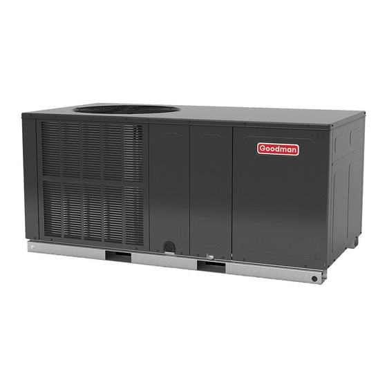
Goodman H Series Installation Instructions Manual

Goodman H Series Installation Instructions Manual

Self-contained package air conditioners and heat pump units with r-410a

Advertisement

I
NSTALLATION
GPC15 / GPH16 (15/16 SEER "H" SERIES)
S
-C
P
ELF
ONTAINED
ACKAGE
W
R-410A
ITH
O
NLY PERSONNEL THAT HAVE BEEN TRAINED TO INSTALL
(
SERVICE OR REPAIR
HEREINAFTER
SPECIFIED IN THIS MANUAL SHOULD SERVICE THE EQUIPMENT
MANUFACTURER WILL NOT BE RESPONSIBLE FOR ANY INJURY OR
PROPERTY DAMAGE ARISING FROM IMPROPER SERVICE OR SERVICE
. I
PROCEDURES
F YOU SERVICE THIS UNIT
RESPONSIBILITY FOR ANY INJURY OR PROPERTY DAMAGE WHICH MAY
. I
,
RESULT
N ADDITION
IN JURISDICTIONS THAT REQUIRE ONE OR
MORE LICENSES TO SERVICE THE EQUIPMENT SPECIFIED IN THIS
,
MANUAL
ONLY LICENSED PERSONNEL SHOULD SERVICE THE
. I
EQUIPMENT
MPROPER INSTALLATION
REPAIR OF THE EQUIPMENT SPECIFIED IN THIS MANUAL
,
ATTEMPTING TO INSTALL
ADJUST
EQUIPMENT SPECIFIED IN THIS MANUAL WITHOUT PROPER TRAINING
MAY RESULT IN PRODUCT DAMAGE
.
INJURY OR DEATH
ATTENTION INSTALLING PERSONNEL
Prior to installation, thoroughly familiarize yourself with
this Installation Manual. Observe all safety warnings. Dur-
ing installation or repair, caution is to be observed.
It is your responsibility to install the product safely and to
educate the customer on its safe use.
RECOGNIZE THIS SYMBOL
AS A SAFETY PRECAUTION.
"IMPORTANT - This product has been designed and manufactured to meet ENERGY STAR®
criteria for energy efficiency when matched with appropriate coil components. However,
proper refrigerant charge and proper air flow are critical to achieve rated capacity and
efficiency. Installation of this product should follow the manufacturer's refrigerant charging
and air flow instructions. Failure to confirm proper charge and air flow may reduce
energy efficiency and shorten equipment life."
IOG-3011D
02/2018
All information contained herein is subject to change without notice.
I
NSTRUCTIONS
A
C
IR
ONDITIONERS AND
,
ADJUST
, "
")
SERVICE
THE EQUIPMENT
. T
HE
,
YOU ASSUME
,
,
ADJUSTMENT
SERVICING OR
,
OR
,
SERVICE OR REPAIR THE
,
,
PROPERTY DAMAGE
PERSONAL
Goodman Manufacturing Company, L.P.
5151 San Felipe, Suite 500, Houston, TX 77056
www.goodmanmfg.com
© 2015-2018 Goodman Manufacturing Company, L.P.
H
P
EAT
UMP
,
These installation instructions cover the outdoor installa-
tion of self contained package air conditioner and heating
units. See the Specification Sheets applicable to your model
for information regarding accessories.
*NOTE: Please contact your distributor or our website for
the applicable Specifications Sheets referred to in this
manual.
U
NITS

Advertisement

Table of Contents
loading

Summary of Contents for Goodman H Series

  • Page 1 Failure to confirm proper charge and air flow may reduce energy efficiency and shorten equipment life.” Goodman Manufacturing Company, L.P. IOG-3011D 5151 San Felipe, Suite 500, Houston, TX 77056 02/2018 www.goodmanmfg.com © 2015-2018 Goodman Manufacturing Company, L.P. All information contained herein is subject to change without notice.
  • Page 2: Table Of Contents

    AIR FLOW MEASUREMENT AND ADJUSTMENT ..10 TO THE INSTALLER ........... 2 ADJUSTING SPEED TAP FOR INDOOR SHIPPING INSPECTION ........2 BLOWER MOTOR ........... 10 Checking Product Received ......2 Message to the Homeowner ......3 EXPANSION VALVE (TXV) SYSTEM REPLACEMENT PARTS ........
  • Page 3: Message To The Homeowner

    MESSAGE TO THE HOMEOWNER These instructions are addressed primarily to the installer; however, useful maintenance information is included and should be kept, after installation, for future reference. REPLACEMENT PARTS Ordering Parts When reporting shortages or damages, or ordering repair parts, give the complete unit model and serial numbers as stamped on the unit’s nameplate.
  • Page 4: Epa Regulations

    72 hours of operation. Rated performance is delivered at the specified airflow. See outdoor unit specifica- tion sheet for split system models or product specification sheet for packaged and light commercial models. Specification sheets can be found at www.goodmanmfg.com for Goodman brand products or www.amana-hac.com for Amana brand ®...
  • Page 5: Rooftop Installation

    The unit should be set on a solid, level foundation - preferably a concrete 36" slab at least 4 inches thick. The slab should be above ground level and surrounded by a graveled area for good drainage. Any slab used as a unit’s foundation should not adjoin the building as it is possible that sound and vibration may be transmitted to the structure.
  • Page 6: Plenum Application

    SQUARE TO ROUND DUCT CONVERTER PANEL OUTER FLANGE 1000 1500 2000 2500 3000 3500 STARTER FLANGE Airflow - SCFM FIGURE 3 FIGURE 4 Plenum Application A suitable plenum or square duct must be constructed. The duct cross-sectional area should be determined by industry duct sizing manuals or air duct calculators.
  • Page 7: High Voltage Wiring

    accordance with local codes, or in absence of local codes, with N.E.C ANSI/ NFPA NO. 70-1984 or latest edition by using WARNING ground lug in the control box. HIGH VOLTAGE Fuses or HACR type circuit breakers may be used where ISCONNECT POWER BEFORE SERVICING OR INSTALLING codes permit.
  • Page 8: Heat Pump Start-Up Procedure

    8. Turn the thermostat system switch to “OFF” and disconnect all power when servicing the unit. WARNING HIGH VOLTAGE ISCONNECT POWER BEFORE SERVICING OR INSTALLING Heat Pump Start-Up Procedure THIS UNIT. ULTIPLE POWER SOURCES MAY BE PRESENT. FAILU TO DO SO MAY CAUSE PROPERTY DAMAGE, PERSONAL INJURY O 9.
  • Page 9: Components

    19. Make sure the unit is free of “rattles”, and the tubing in the unit is free from excessive vibration. Also make sure tubes or lines are not rubbing against each other or sheet metal surfaces or edges. If so, correct the trouble. 20.
  • Page 10: Defrost Control

    When the heat pump is on the heating cycle, the outdoor coil is functioning as an evaporator. The temperature of the refrigerant in the outdoor coil must be below the temperature of the outdoor air in order to extract heat from the air. Thus, the greater the difference in the outdoor temperature and the outdoor coil temperature, the greater the heating capacity of the heat pump.
  • Page 11: Expansion Valve (Txv) System

    The leads are factory connected as follows: Green to T1, Yellow to T2, and White to T3. T1 is the low speed setting and is dedicated to fan-only mode. T2 is medium speed cooling and T3 is medium speed heating. T4 is high speed cooling and T5 is high speed heating.
  • Page 12: Two Speed Application (Gpc1560/Gph1642-60)

    1. Purge gauge lines. Connect service gauge manifold to access fittings. Run GPC15 system at least 10 minutes to allow pressure to stabilize. Design superheat @ 95 °F 2. Temporarily install thermometer on liquid (small) line near liquid line access outdoor ambient temperature fitting with adequate contact and insulate for best possible reading.
  • Page 13: Inadequate Air Volume Through Indoor Coil

    be clean, and sufficient air volume must pass through the indoor coil to prevent excessive discharge pressure, and high pressure WARNING cut out. HIGH VOLTAGE Outside Air Into Return Duct ISCONNECT POWER BEFORE SERVICING OR INSTALLING THIS UNIT. ULTIPLE POWER SOURCES MAY BE PRESENT. FAILU Do not introduce cold outside air into the return duct of a TO DO SO MAY CAUSE PROPERTY DAMAGE, PERSONAL INJURY O heat pump installation.
  • Page 14: Blower Performance Gp* 15/16 Seer

    GPC15/GPH16[24-36]H41 BLOWER PERFORMANCE E.S.P. (In. of H Volts Model Speed Watts T2 / T3 Watts 1231 1179 1127 1074 1022 T4 / T5 Watts Watts T2 / T3 Watts 1231 1179 1127 1074 1022 T4 / T5 Watts 1048 Watts 1123 1068 1014...
  • Page 15 GPC15/GPH16[24-36]H41 BLOWER PERFORMANCE E.S.P. (In. of H Model Speed Volts 1181 1146 1112 1062 1022 Watts 1410 1366 1328 1286 1248 1195 1155 1115 T2 / T3 Watts 1637 1605 1561 1527 1484 1436 1390 1345 T4 / T5 Watts 1165 1122 1080...
  • Page 16: Troubleshooting Chart

    TROUBLESHOOTING CHART HIGH VOLTAGE! ISCONNECT POWER BEFORE SERVICING OR INSTALLING THIS UNIT ULTIPLE POWER WARNING SOURCES MAY BE PRESENT AILURE TO DO SO MAY CAUSE PROPERTY DAMAGE PERSONAL INJURY OR DEATH POSSIBLE CAUSE REMEDY SYMPTOM High head - low suction a.
  • Page 17 PACKAGE UNITS - HEAT PUMP AND AC UNITS HOMEOWNER’S ROUTINE MAINTENANCE RECOMMENDATIONS We strongly recommend a bi-annual maintenance checkup be performed by a qualified service agency before the heating and cooling seasons begin. An alternate cleaning method is to use one of the products EPLACE OR LEAN ILTER...
  • Page 18: Start-Up Checklist

    Start-up Checklist *Store in job file Air Conditioning & Heating Date: ___________________________________ Location: __________________________________________ Model Number: ___________________________________ __________________________________________ Serial Number: ___________________________________ __________________________________________ Technician: ___________________________________ Unit #: __________________________________________ Pre Start-Up (Check each item as completed) Verify all packaging material has been removed. Remove all shipping brackets per installation instructions.
  • Page 19 Start-up Checklist Air Conditioning & Heating Start-Up (Insert the values as each item is completed.) ELECTRICAL Supply Voltage L1 - L2 L2 - L3 L3 - L1 Circuit 1 Compressor Amps Circuit 2 Compressor Amps Blower Amps Condenser Fan Amps Fan 1 Fan 2 Fan 3...
  • Page 20 You can also scan the QR code on the right for the product brand you purchased to be directed to the Product Registration page. Goodman Manufacturing Company, L.P. 5151 San Felipe, Suite 500, Houston, TX 77056 www.goodmanmfg.com © 2015-2018 Goodman Manufacturing Company, L.P.

Table of Contents