Table of Contents
Advertisement
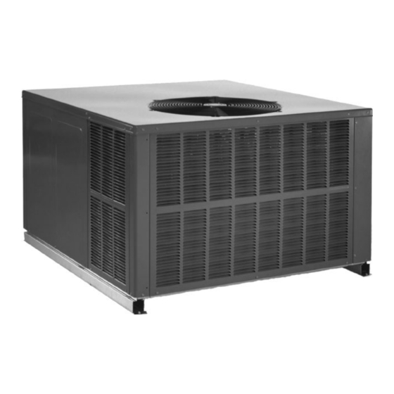
SINGLE PACKAGE GAS-ELECTRIC
Prior to installation, thoroughly familiarize yourself with this Installation Manual. Observe all safety warnings. During
It is your responsibility to install the product safely and to educate the customer on its safe use.
These installation instructions
installation of single package gas electric heating and
cooling units. See the Product Data Book applicable to
your model* for information regarding accessories.
10-245
INSTALLATION & OPERATING
INSTRUCTIONS for
GPG10 & GPG12
HEATING & COOLING UNIT
Affix this manual and Users Information Manual adjacent to the unit.
RECOGNIZE THIS SYMBOL AS A SAFETY PRECAUTION.
ATTENTION INSTALLING PERSONNEL
installation or repair, caution is to be observed.
cover the outdoor
Goodman Manufacturing Company, L.R
2550 North Loop West, Suite 400, Houston, TX 77092
www.qoodmanmfg.com
©2004 Goodman Manufacturing Company, L.R
This Forced Air Central Unit Design Complies With
Requirements Embodied in The American National
Standard / National Standard of Canada Shown Below.
ANSI Z21.47-CSA-2.3 Central Furnaces
'NOTE: Please contact your distributor or our
website for the applicable product data
book referred to in this manual.
US
6/04
Advertisement
Table of Contents

Subscribe to Our Youtube Channel
Related Manuals for Goodman GPG10


Summary of Contents for Goodman GPG10
- Page 1 INSTALLATION & OPERATING INSTRUCTIONS for GPG10 & GPG12 SINGLE PACKAGE GAS-ELECTRIC HEATING & COOLING UNIT Affix this manual and Users Information Manual adjacent to the unit. This Forced Air Central Unit Design Complies With Requirements Embodied in The American National Standard / National Standard of Canada Shown Below.
-
Page 3: Replacement Parts
REPLACEMENT PARTS ORDERING PARTS HEATING UNIT SHOULD NOT BE UTILIZED WITHOUT REASONABLE, ROUTINE, When reporting shortages or damages, or ordering repair parts, INSPECTION, MAINTENANCE AND SUPERVISION. |F THE BUILIDNG IN WHICH ANY give the complete unit model and serial numbers as stamped SUCH DEVICE IS LOCATED WILL BE VACANT, CARE SHOULD BE TAKEN THAT on the unit's nameplate. -
Page 4: Unit Location
UNIT LOCATION TO PREVENT POSSIBLE EQUIPMENT DAMAGE, PROPERTY DAMAGE, PERSONAL INJURY OR DEATH, THE FOLLOWING BULLET POINTS MUST BE OBSERVED WHEN INSTALLING THE UNIT. IMPORTANT NOTE: Remove wood shipping rails prior to installa- tion of the unit. A L L INSTALLATIONS: •... -
Page 5: Rigging Details
Carefully inspect the unit for damage including damage to the cabinetry. Any bolts or screws which may have loosened in transit must be re-tightened. In the event of damage, the receiver should: 1. Make notation on delivery receipt of any visible damage to shipment or container. -
Page 6: Gas Piping
GAS PIPING Natural Gas Connection IMPORTANT NOTE: This unit is factory set to operate on natural gas at the altitudes shown on the rating plate. TO AVOID PROPERTY DAMAGE, PERSONAL INJURY OR DEATH WHEN EITHER USING PROPANE GAS ALONE OR AT HIGHER ALTITUDES, OBTAIN AND INSTALL THE PROPER CONVERSION KIT(S). -
Page 7: Propane Gas Installations
dissipated in the air. Be certain there is no open flame in the vicinity during air bleeding procedure. The unit is placed in operation by closing the main electrical disconnect switch for the unit. PROPANE GAS INSTALLATIONS TO AVOID PROPERTY DAMAGE, PERSONAL INJURY OR DEATH DUE TO FIRE OR EXPLOSION CAUSED BY A PROPANE GAS LEAK, INSTALL A GAS DETECTING WARNING DEVICE. -
Page 8: Electrical Wiring
etc. Consult the Instruction Sheet packaged with thermostat for Sizing Between First and Second Stage Regulator Maximum Propane Capacities listed are based on 1 PSIG Pressure Drop at 10 mounting instructions. PSIG Setting, Capacities in 1.000 BTU/HR All units have one stage of heating and one stage of mechanical cooling. -
Page 9: Circulating Air And Filters
All line voltage connections must be made through weatherproof fittings. All exterior power supply and ground wiring must be in approved weatherproof conduit Low voltage wiring from the unit control panel to the thermostat requires coded cable. See below for ground level and rooftop wiring. Note:Junction box location shown is optional and is for illustration purposes only. -
Page 10: Condensate Drain
Down Discharge Applications To install the flue hood cover and bug screen: 1. Remove the flue hood and bug screen from inside the heat Cut insulation around bottom openings and remove panels from exchanger compartment. the bottom of the unit, saving the screws holding the panels in place. -
Page 11: Startup, Adjustments, And Checks
5. The gas valve deenergizes. The induced draft blower continues operation for a 29-second post-purge. 6. ignition control begins timing the HEAT FAN OFF delay. There is an adjustable HEAT FAN OFF delay of TO AVOID PROPERTY DAMAGE, PERSONAL INJURY OR DEATH DUE TO FIRE OR EXPLOSION, A QUALIFIED SERVICER MUST INVESTIGATE THE REASON FOR approximately 120/135/150 seconds (factory set at 150). - Page 12 7. Wait five minutes to clear out any gas. 8. Smell for gas, including near the ground. This is important because some types of gas are heavier than air. If you have waited five minutes and you do smell gas, immediately follow the warnings on page 3 of this manual.
- Page 13 Main Burner Flame Check Flames should be stable, soft and blue (dust may cause orange tips but they must not be yellow) and extending directly outward from the burner without curling, floating or lifting off. Temperature Rise Check Check the temperature rise through the unit by placing thermometers in supply and return air registers as close to the unit as possible.
-
Page 14: Troubleshooting
function of outdoor ambient temperature and return air diagnostic LED indicates an external lockout, perform the temperature of the conditioned space. It is the installing following checks; contractors responsibility to ensure the proper refrigerant • Check the supply and manifold pressures superheat at the compressor is adjusted for each application. -
Page 15: Maintenance
Flame Detected with Gas Valve Closed CLEAN OUTSIDE COIL (QUALIFIED SERVICER ONLY) If flame is detected with the gas valve deenergized, the The coil with the outside air flowing over it should be inspected combustion and air circulator blowers are energized. The annually and cleaned as frequently as necessary to keep the diagnostic fault code is five (5) flashes for this condition. -
Page 16: Accessories And Functional Parts
ALWAYS VERIFY PROPER OPERATION AFTER SERVICING. For further information on the yearly inspection, consult the User Manual. It is recommended that a qualified servicer inspect and service the unit at least once each year. Turn the unit on at the thermostat. Wait a few minutes, since any dislodged dust will alter the normal flame appearance.
Need help?
Do you have a question about the GPG10 and is the answer not in the manual?
Questions and answers