
Related Manuals for janitza RCM 202-AB


Summary of Contents for janitza RCM 202-AB
- Page 1 RESIDUAL CURRENT MEASUREMENT DEVICE RCM 202-AB User manual and technical data Janitza electronics GmbH Vor dem Polstück 6 D-35633 Lahnau, Germany Support Tel. +49 6441 9642-22 E-Mail: info@janitza.de www.janitza.de...
- Page 2 RCM 202-AB www.janitza.de...
-
Page 3: Table Of Contents
Connection assignment ..............20 Application example ................22 Application example RCM 202-AB in stand-alone mode ....... 22 Application example analog outputs (interface 4 … 20 mA) ....22 Application example analog outputs and UMG 96RM-E ......23 ... - Page 4 RCM 202-AB www.janitza.de Display and operating elements ............27 10.1 Display and keys ..................27 10.2 Meaning of the status LED ..............29 10.3 Key functions ..................29 10.4 Menu release ..................29 ...
- Page 5 The status LED flashes red ..............56 14.1.6 The status LED lights up red ..............57 14.2 Replacement of a defective RCM 202-AB ..........58 14.2.1 Removal of a defective RCM 202-AB ............ 58 14.2.2 Installation of a new RCM 202-AB ............
- Page 6 RCM 202-AB www.janitza.de...
-
Page 7: Information About Using This User Manual
This user manual is a part of the product and makes reference to other devices from Janitza electronics GmbH. Only the names of the respective device series are spec- ified, but not all the associated types. Read this user manual before using the device. -
Page 8: Safety Instructions
RCM 202-AB www.janitza.de Safety instructions Symbols used WARNING These symbols and the word “warning” are used when there is possible danger to life and limb. Symbols are also used in these instructions that refer directly to the source of danger. -
Page 9: Purpose - Intended Use
The external signal current circuits used in the monitoring system shall be secondary current circuits. Any use of the RCM 202-AB that differs from the description in this manual is consid- ered improper use and may affect the protection provided by the device. -
Page 10: Scope Of Delivery
Scope of delivery The following components are part of the scope of delivery of an individual device: 1 x RCM 202-AB 1 set of plugs (on the device) 1 x user manual Check the scope of delivery to ensure it is complete and immediately report any dam- age or missing content to the manufacturer/sales partner. -
Page 11: Device Dimensions
RCM 202-AB Device dimensions Fig. 2: Device dimensions in mm Labeling Various labels are applied on the RCM 202-AB with the following information: Manufacturer Serial number and item number Technical data (short form) CE mark RCM 202-AB... -
Page 12: Functions
Functions Basic functionality The main functions of the RCM 202-AB are: Residual current measurement via a connected current measurement trans- former (max. 2 current measurement transformers) Transformer connection monitoring for wire breaks or short circuit per channel ... -
Page 13: Current Measurement Transformer Monitoring
The RCM 202-AB evaluates currents from up to two current measurement transform- ers at the same time. For each active channel, the RCM 202-AB continuously checks the connected transformer for short circuit or wire breaks. If a short circuit or wire break occurs on the transformers, an error message is output on the display as well as on the communication interfaces and the LED status flashes red. -
Page 14: Warning And Alarm Thresholds
RCM 202-AB www.janitza.de 6.2.1 Warning and alarm thresholds Warning and alarm thresholds are parameterizable thresholds, which can be adapted to the currents to be monitored. They can be adjusted separately for each channel. When reaching these thresholds, warning or alarm messages are sent. The status LED lights up yellow and channel-related text messages are shown on the display. -
Page 15: Delay Times
Reset delay time for warning and alarm messages If there are no more messages, the RCM 202-AB resets the warning and alarm mes- sages. The reset delay time (t ) for the warning and alarm messages can be param- eterized and is needed to ignore brief fluctuations. -
Page 16: Extreme Value Storage
RCM 202-AB according to schedule (e.g. monthly) in order to read out the data sets. During a connection, the data collected is read and sorted in the data- base so that a complete history exists. -
Page 17: Rs485 Interface (Modbus)
It is possible to manually delete the measured value memory via the configuration menu. RS485 interface (Modbus) The RCM 202-AB has a Modbus interface (RS485) and works with the Modbus RTU protocol as a slave. The device address 1 and the baud rate of 19200 baud are fac- tory-set. - Page 18 The twisted wires of the cable must be connected to terminals “B+” and “A-”. In order to equalize the potential differences between multiple RCM 202-AB, the ground ter- minals of all devices on the bus must be connected together. The second twisted wire pair of the bus cable is used for potential equalization.
-
Page 19: Digital Outputs
(DC 12 … 24 V). In the configuration menu of the RCM 202-AB, the measuring range (total current) can be scaled. In systems with low total currents, this makes it possible for the measured total current to be evaluated in a more precise manner. -
Page 20: Connection Assignment
RCM 202-AB www.janitza.de Connection assignment Fig. 8: Circuit diagram of the RCM 202-AB RCM 202-AB... - Page 21 I2 – L brown) Power supply connection Supply voltage AC 90 ... 230 V (N) Supply voltage AC 90 ... 230 V (L) Tab. 3: Connection assignment RCM 202-AB Bus termination TERM switch Switch position Resistance Resistance (120 Ω) switched on...
-
Page 22: Application Example
Fig. 9: Connection of two relays to the digital outputs Application example analog outputs (interface 4 … 20 mA) Fig. 10: Connection of a display device and a PLC to the analog outputs (Power supply: Janitza power supply unit, art. no. 16.05.012) RCM 202-AB... -
Page 23: Application Example Analog Outputs And Umg 96Rm-E
RCM 202-AB Application example analog outputs and UMG 96RM-E Application example analog outputs and UMG 96RM-E Janitza power supply unit (art. no. 16.05.012) required! Janitza power supply unit (art. no. 16.05.012) required! RCM 202-AB RCM 202-AB... -
Page 24: Application Examples Via Modbus (Rs485 Interface)
RCM 202-AB www.janitza.de Application examples via Modbus (RS485 interface) Fig. 11: Application example – PLC Fig. 12: Application example – Measurement devices Fig. 13: Application example – Modbus TCP Fig. 14: Application example RS232/RS485 RCM 202-AB... -
Page 25: Assembly, Commissioning And Configuration
Assembly (initial installation) The RCM 202-AB is installed in distribution boards and switchgears on a top hat rail (35 mm) according to DIN EN 60715. Requirements: The current measurement transformers are already installed on the cables to be monitored. -
Page 26: Commissioning
NOTE The device address 1 and the baud rate of 19200 baud are factory-set. If the RCM 202-AB is the first or last device in the Modbus line, the termina- tion resistor must be set. The ground terminals of all RS485 connections of multiple RCM 202-AB must be connected with the ground wire of the cable. -
Page 27: Configuration (Parameterization)
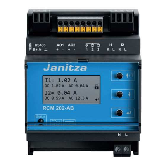
Current measured values of the current Menu release measurement transformer or text mes- Status LED sage Keys If the RCM 202-AB is in normal mode, e.g. without any errors or faults (see Fig. 15), the “main screen” is shown on the display: RCM 202-AB... - Page 28 RCM 202-AB www.janitza.de 1st row: Current measured value of current measurement transformer 1 2nd row: Direct current portion and alternating current portion of the meas- ured residual current of current measurement transformer 1 3rd row: Current measured value of current measurement transformer 2...
-
Page 29: Meaning Of The Status Led
10.2 Meaning of the status LED Condition of LED Meaning No power supply Green RCM 202-AB ready for operation. Flashing green RCM 202-AB is started. Yellow Response values are exceeded, error detected Red or flashing red Error, RCM 202-AB faulty. -
Page 30: Operation
11.1 Release and block of parameterization mode Release of parameterization mode Initial situation: The RCM 202-AB is in normal mode, the “main screen” appears on the display. Press . The main menu opens and menu item “1.Basic settings” is dis- played with a dark background. -
Page 31: Operating Steps For Displaying And Changing Values In The Menu
NOTE Parameterization mode is not blocked when “000000” is set as the pass- word. Initial situation: The RCM 202-AB is in normal mode. to select the menu item until the “main screen” ap- pears on the display again. Wait 60 seconds. The symbol on the display changes to . - Page 32 Changing the response delay for measurement channel 1 (menu item “response delay” in menu “2.Channel parameters“) Initial situation: The main menu is shown on the RCM 202-AB display and pa- rameterization mode is active. Press . The main menu is displayed.
-
Page 33: Operating Steps For Checking The Monitoring Function
The performance of the test is saved with the time stamp and can be dis- played in the menu “6.Functional test”. Initial situation: The main screen is shown on the RCM 202-AB display. Press for at least 3 seconds. An internal test signal for testing the mon- itoring function is generated. -
Page 34: Configuration Menu
RCM 202-AB www.janitza.de Configuration menu Main menu 1.Basic settings 1.Basic settings LCD contrast 2.Channel parameter Change date/time 3.Communication Language 4.Measured value memory Parameter release 5.Min/max values Change password 6.Functional test 7.Service 8.Factory setting 9.Information 10.Restart 2.Channel parameter Channel 1 Channel active ... - Page 35 RCM 202-AB 5.Min/max values 5.Min/max values 1 Channel 1 Max value = 0.02 A Channel 2 Max value time 24.02.2018 14:08 PM Min value = 0.00 A Min value time 24.02.2018 10:02 AM Delete values 6.Functional test Test interval OFF Last test ...
-
Page 36: Menu: 1.Basic Settings
RCM 202-AB www.janitza.de 12.1 Menu: 1.Basic settings 1.Basic settings LCD contrast Change date/time Language Parameter release Change password Fig. 17: “1.Basic settings” menu The menu items make it possible to set the following: Display contrast, Release of parameterization mode (password entry), ... -
Page 37: Menu Item: Language
RCM 202-AB 12.1.3 Menu item: Language ATTENTION After selecting the required language with and confirming with , the selected language is activated immediately! Language deutsch english español ... -
Page 38: Channel Parameter
RCM 202-AB www.janitza.de Shown on the dis- Set values/control com- Remark play mands Enter the new pass- Activate editing the number word with Change password 6-digit number sequence Confirm the set number with 0 0 0 0 0 Enter the new pass-... -
Page 39: Menu Item: Channel Active
RCM 202-AB Menu items: Channel 1 and channel 2 Channel 1 Channel 2 Channel active Channel active Transformer type = DW18 Transformer type = DW18 Monitoring active Monitoring active Warning th. I = 3.00 A Warning th. I = 3.00 A Warning th. I DC = 3.00 A Warning th. I DC = 3.00 A Warning th. I AC2k = 3.00 A Warning th. I AC2k = 3.00 A Warning th. I AC20k = 3.00 A ... -
Page 40: Menu Item: Monitoring Active
RCM 202-AB www.janitza.de 12.2.3 Menu item: Monitoring active Setting option: Transformer monitoring activation Shown on the dis- Set values/control com- Remark play mands Monitoring Monitoring activated active Monitoring deactivated 12.2.4 Menu items: Warning th. I to warning th. I AC50... -
Page 41: Menu Items: Alarm Th. I To Alarm Th. I Ac50
RCM 202-AB 12.2.5 Menu items: Alarm th. I to alarm th. I AC50 NOTE The response values for the alarm thresholds must be set higher than the response values for the warning thresholds. Setting option: Threshold values for the triggering of alarm messages A message appears if the set value is exceeded (display, Modbus, if parameterized: digital output 1 and/or 2). -
Page 42: Menu Item: Autom. Reset
RCM 202-AB www.janitza.de 12.2.6 Menu item: Autom. reset Setting option: Activation of the automatic reset of warning and alarm mes- sages after the end of the warning or alarm condition Shown on the dis- Set values/control com- Remark play mands Autom. -
Page 43: Menu Items: Digital Output 1 And Digital Output 2
RCM 202-AB 12.2.10 Menu items: Digital output 1 and digital output 2 Setting option: Message source for signaling via the digital output Shown on the dis- Set values/control com- Remark play mands Warning Message source activated threshold I …... -
Page 44: Menu: 3.Communication
Communication interface RS485 (Modbus). 12.3.1 Menu item: Modbus active ATTENTION The RCM 202-AB is a Modbus slave. The communication interface must be deactivated when the RCM 202-AB is not connected with a Modbus master. Setting option: Activation of the RS485 interface (Modbus) -
Page 45: Menu Item: Address
RCM 202-AB 12.3.2 Menu item: Address NOTE Different addresses must be assigned to the RCM 202-ABs in the same bus segment. Setting option: Modbus address of the RCM 202-AB Shown on the dis- Set values/control com- Remark play mands Address = 1 1 …... -
Page 46: Menu Item: Interval
RCM 202-AB www.janitza.de 12.4.2 Menu item: Interval Setting option: Measurement interval for averaging (without password) Shown on the dis- Set values/control com- Remark play mands 60 s, 300 s, 600 s, 900 s, Interval = 900 s 1800 s, 3600 s 12.4.3 Menu item: Delete record ATTENTION... -
Page 47: Menu Items: Channel 1 And Channel 2
RCM 202-AB 12.5.1 Menu items: Channel 1 and channel 2 5.Min/max values 1 5.Min/max values 2 Max value = 0.02 A Max value = 0.02 A Max value time Max value time 24.02.2018 14:08 PM 24.02.2018 14:08 PM Min value ... -
Page 48: Menu: 6.Functional Test
RCM 202-AB www.janitza.de Setting option: Display and deletion of the saved extreme values per channel Shown on the dis- Remark play 5.Min/max values n n = Number of the measurement channel whose extreme values are displayed. Max value Highest measured residual current (pulsating current) since... -
Page 49: Menu Item: Last Test
Remark play Last test The time stamp is set after the test for the monitoring func- tion of RCM 202-AB is formed by pressing dd.mm.yyyy HH:MM (dd = day, mm = month, yyyy = year, HH = hour, MM = minute) 12.7... -
Page 50: Menu Item: Transformer Analysis
In progress The transformer analysis is complete. Ended The RCM 202-AB does not provide feedback about the re- sult of the analysis. If no error message is shown on the main screen, all characteristics can be determined. RCM 202-AB... -
Page 51: Menu Item: Power Frequency
ATTENTION No additional confirmation prompts are displayed when parameterization mode is active. After the menu item is selected, the RCM 202-AB restarts. Then check the set values and the control commands of the RCM 202-AB according to the system to be monitored and depending on the circuit of its connections. -
Page 52: Menu: 9.Information
Manufacturer, Device denomination and revision number, Serial number (“SN”), Firmware version, Item number (“P/N”) of the RCM 202-AB. 12.10 Menu: 10.Restart By selecting this menu with , the RCM 202-AB is restarted. In this way, for example, it is possible to delete error messages on the display that were not reset after eliminating the fault or correcting the error. -
Page 53: Servicing
Fault messages and erroneous functions are displayed by the LED and text mes- sages of the RCM 202-AB. A visual inspection is to be performed in the course of the maintenance and inspection cycle for stationary electrical systems. This includes ad- herence to the installation conditions, tight fit of the plug connector and a check for visible damages. -
Page 54: Troubleshooting
Error pattern: The RCM 202-AB housing is warm NOTE The RCM 202-AB housing warms up during operation up to 45 °C. Carry out the following troubleshooting only when the housing temperature is higher than 45 °C. Cause:... -
Page 55: The Status Led Is Off
Check the plug for the power supply on the bus connections on the RCM 202- AB for tight fit. Check the power supply of the RCM 202-AB. If necessary, replace the RCM 202-AB (see chapter 14.2 on page 58). 14.1.2 The status LED flashes green Text message:... -
Page 56: The Status Led Flashes Yellow
14.1.5 The status LED flashes red Text message: Overflow Cause: Measuring range exceeded Remediation: Check the currents to be measured with a multimeter. If all currents are less than 20 A, the RCM 202-AB is defective and must be replaced. RCM 202-AB... -
Page 57: The Status Led Lights Up Red
If an electrically conductive connection does not exist, replace the current measurement transformer. If there is an electrically conductive connection, replace the RCM 202-AB. After completing the work, reconnect the plug of the current measurement transformer to the RCM 202-AB. -
Page 58: Replacement Of A Defective Rcm 202-Ab
It is possible to change the device during operation without turning off the consumers. To prevent dangerous contact voltage on the terminals of the RCM 202-AB and to prevent the triggering of malfunctions, the sequence described below must be ob- served for the removal and reinstallation. -
Page 59: Warranty And Liability
AB is ready for operation. The LED lights up green and the text messages display the current operating status of the monitored system. If necessary, configure the RCM 202-AB according to the system to be mon- itored and depending on the circuit of its connections. -
Page 60: Declaration Of Conformity
The device has a CE mark. It fulfills the low voltage directive 2006/95/EC and the EMC Directive 2004/108/EC (for the considered standards, see chapter 19 on page 60). The full text of the Declaration of Conformity can be requested from Janitza electronics GmbH. Technical data 19.1... - Page 61 Menu languages German, English, Spanish Date and time With RTC, stored in the non-volatile memory Parameterization On RCM 202-AB in the configuration menu Messages Display, LED, Modbus, digital outputs Measured value memory 18,725 datasets (circular buffer) With date and time Examples: Shielded cable 0.75 mm...
- Page 62 RFI field strength 30 ... 1000 MHz IEC/CISPR11/EN 55011 Radiated interference voltage 0.15 ... 30 IEC/CISPR11/EN 55011 Standards The RCM 202-AB fulfills the requirements according to EN 62020:1998+A1:2005 (VDE 0663):2005 Ambient conditions Ambient temperature during operation -5 ... +55°C (23°F…131°F) Ambient temperature during storage -25 ...
-
Page 63: Rcm 202-Ab Plug
Approx. 170 g (0.375 lb) Connection type/cable Series terminal/copper Connection cross section single-wire/finely 0.2 ... 4 mm /0.2 ... 1.5 mm (AWG 24-15) stranded 19.2 RCM 202-AB plug Connection Quan- Designation tity Connector, RS485 (Modbus) Socket plug, 3-pin Connector, Analog and digital out-... - Page 64 RCM 202-AB www.janitza.de Connection type/cable Series terminal/copper Connection cross section single-wire/finely 0.2 ... 4 mm /0.2 ... 1.5 mm (AWG 24-15) stranded 19.2 RCM 202-AB plug Connection Quan- Designation tity Connector, RS485 (Modbus) Socket plug, 3-pin Connector, Analog and digital out-...
- Page 65 600:1 18000 KBU 812D 80 x 120 • 600:1 18000 Tab. 5: Current measurement transformer for RCM 202-AB Janitza electronics GmbH RCM 202-AB Residual current monitoring device Vor dem Polstück 6 User manual 35633 Lahnau, Germany Issued by: © Janitza electronics GmbH...
- Page 66 RCM 202-AB www.janitza.de...
- Page 67 RCM 202-AB...
- Page 68 600:1 18000 KBU 812D 80 x 120 • 600:1 18000 Tab. 5: Current measurement transformer for RCM 202-AB Janitza electronics GmbH RCM 202-AB Residual current monitoring device Vor dem Polstück 6 User manual 35633 Lahnau, Germany Issued by: © Janitza electronics GmbH...
Need help?
Do you have a question about the RCM 202-AB and is the answer not in the manual?
Questions and answers