Table of Contents
Advertisement
Advertisement
Table of Contents

Related Manuals for janitza UMG 96RM-P


Summary of Contents for janitza UMG 96RM-P
- Page 1 Power Analyser UMG 96RM-P UMG 96RM-CBM Operating instructions and technical data Janitza electronics GmbH UMG 96RM-CBM UMG 96RM-P Vor dem Polstück 1 D-35633 Lahnau Support tel. 0049 6441 9642-22 Fax 0049 6441 9642-30 E-mail: info@janitza.com Internet: http://www.janitza.com...
- Page 2 UMG 96RM-P/-CBM Table of contents General Display mode Incoming goods inspection Programming mode Scope of delivery UMG 96RM-P or -CBM Parameters and measured values Available accessories Configuration Product description Applying the supply voltage Proper use Current and voltage transformers Features of the UMG 96RM-P/-CBM...
- Page 3 UMG 96RM-P/-CBM Digital outputs Impulse output Comparators and monitoring threshold values Service and maintenance Service Device calibration Calibration intervals Firmware update Battery Battery monitoring function Replacing the battery Error messages Technical data Parameters of functions Table 1 - Parameter list...
-
Page 4: General
The following pictograms are used in this manual: the legally binding, written consent of Janitza electronics GmbH, Vor dem Polstück 1, D 35633 Lahnau, Germany. Dangerous voltage! Trademarks Risk of death or serious injury. Disconnect... - Page 5 UMG 96RM-P/-CBM Application notes Please read these operating instructions and all other When using the device, the legal and safety regulations required for the respective application must also be publications that must be consulted in order to work with this product (particularly for installation, operation observed.
-
Page 6: Incoming Goods Inspection
UMG 96RM-P/-CBM Incoming goods inspection About these operating instructions These operating instructions are part of the product. The proper and safe operation of this device • Read the operating instructions prior to using requires appropriate transport, proper storage, the device. -
Page 7: Scope Of Delivery Umg 96Rm-P Or -Cbm
UMG 96RM-P/-CBM Scope of delivery UMG 96RM-P or -CBM Quantity Item no. CBM- Designation Expansion Expansion 52.22.xxx* UMG 96RM-P or UMG 96RM-CBM* 52.22.251 Mounting brackets 33.03.160 Operating instructions 51.00.116 CD with the following contents - GridVis programming software - GridVis functional description 10.01.855... -
Page 8: Available Accessories
UMG 96RM-P/-CBM Available accessories Item no. Designation 21.01.058 Battery 3V, TYP CR2032 (according to UL1642) 29.01.907 Seal, 96 x 96 15.06.015 Interface converter RS485 <-> RS232 15.06.025 Interface converter RS485 <-> USB 13.10.539 D-sub Profibus connector... -
Page 9: Product Description
(Modbus RTU) voltages of up to 300V relative to earth and surges in overvoltage category III can occur. Profibus The current measurement inputs of the UMG 96RM-P/ -CBM are connected via external ../1A or ../5A current transformers. -
Page 10: Features Of The Umg 96Rm-P/-Cbm
• 6 digital outputs and 4 digital inputs and current measurement inputs • USB interface • Frequency range of the mains frequency • Only UMG 96RM-P variant: Profibus interface 45 Hz .. 65 Hz (Profibus DP V0) • Measurement of harmonics 1 to 40 •... -
Page 11: Measuring Method
(TRMS) of the voltages and currents applied to the measuring inputs. Operating concept There are several ways to program the UMG 96RM-P/ -CBM and retrieve measured values. • Directly on the device using two buttons • Via the programming software of the GridVis •... -
Page 12: Gridvis Network Analysis Software
GridVis network analysis software Connection variants The UMG 96RM-P/-CBM can be programmed and read Connecting a UMG 96RM-P or -CBM to a PC via the USB out using the GridVis network analysis software included interface: in the scope of deliverables. A PC must be connected... - Page 13 UMG 96RM-P/-CBM...
-
Page 14: Assembly
UMG 96RM-P/-CBM Assembly Installation location The UMG 96RM-P/-CBM is suitable for installation in permanent, weatherproof switchboards. Conducting switchboards must be earthed. Installation position The UMG 96RM-P/-CBM must be installed vertically in order to achieve sufficient ventilation. The clearance to the top and bottom must be at least 50 mm and 20 mm at the sides. - Page 15 UMG 96RM-P/-CBM Mounting The UMG 96RM-P/-CBM is fixed using the mounting The fastening is then done when the device is pushed clips found on the side of the switch panel. Before in- in an the clamps lock in place when the screws are ti- serting the device, they should be moved out of the way ghtened.
-
Page 16: Installation
(6 A, type C). Fig. Connection example of the supply voltage • In building installations, the supply to the UMG 96RM-P/-CBM voltage must be provided with a disconnect switch or circuit breaker. • The disconnect switch must be attached near the device and must be easily accessible by the user. -
Page 17: Voltage Metering
UMG 96RM-P/-CBM Voltage metering The UMG 96RM-P/-CBM can be used for voltage In systems without a neutral, measured values that measurement in TN, TT and IT systems. require a neutral refer to a calculated neutral. Voltage measurement in the UMG 96RM-P/-CBM is designed for the 300 V overvoltage category CATIII (4 kV rated pulse voltage). - Page 18 UMG 96RM-P/-CBM Rated mains voltage Lists of the networks and their rated mains voltage in which the UMG 96RM-P/-CBM can be used. Three-phase 4-wire systems Unearthed three-phase, 3-wire systems. with earthed neutral conductor. L-N / 66 V/115 V 66 V...
- Page 19 UMG 96RM-P/-CBM Voltage measurement inputs The UMG 96RM-P/-CBM has three voltage measurement inputs (V1, V2, V3). Overvoltage The voltage measurement inputs are suitable for measurement in networks in which overvoltages of overvoltage category 300V CATIII (4 kV rated pulse voltage) can occur.
- Page 20 • A suitable separator must be provided in order via voltage transformers. to switch off the power to the UMG 96RM-P/-CBM. • The separator must be placed near the UMG 96RM- Attention! P/-CBM, marked for the user and easily accessible.
- Page 21 UMG 96RM-P/-CBM...
- Page 22 UMG 96RM-P/-CBM Connection diagram, voltage measurement • 3p 4w (addr. 509= 0), factory setting • 3p 4wu (addr. 509 = 1) Fig. System with three-phase conductors and a Fig. System with three-phase conductors and neutral conductor. a neutral conductor. Measurement via voltage transformer.
- Page 23 UMG 96RM-P/-CBM • 1p 2w1 (addr. 509 = 4) • 2p 4w (addr. 509 = 3) Fig. Measured values derived from the V2 and Fig. System with uniform phase loading. The V3 voltage measurement inputs are assumed to measured values for the V2 voltage measure- be zero and not calculated.
-
Page 24: Current Measurement Via I1 To I4
UMG 96RM-P/-CBM Current measurement via I1 to I4 The UMG 96RM-P/-CBM is designed to have cur- rent transformers with secondary currents from ../1A and ../5A attached cia terminals I1-I4. The factory de- fault for the current transformer ratio is 5/5A and must be adapted to the current transformer employed if ne- cessary. - Page 25 If a connection is provided for the earthing of secondary windings then this must be connected to the earth. Caution! The UMG 96RM-P/-CBM is not suitable for measuring DC voltages. It is not necessary to configure a connec- tion schematic for the I4 measurement input.
- Page 26 UMG 96RM-P/-CBM Direction of the current The current direction can be individually corrected Current transformer connections! on the device or via the serial interfaces for each phase. The secondary connection of the current In the case of incorrect connection, the current trans- transformer must be short-circuited on this former does not need to be subsequently reconnected.
- Page 27 UMG 96RM-P/-CBM...
- Page 28 UMG 96RM-P/-CBM Connection diagram, current measurement • 3p 4w (addr. 510= 0), factory setting • 3p 2i (addr. 510 = 1) Fig. Measurement in a three-phase net-work Fig. System with uniform phase loading. The with an unbalanced load. measured values for the I2 current measurement input are measured.
- Page 29 UMG 96RM-P/-CBM • 3p 3w (addr. 510 = 4) • 2p 4w (addr. 510 = 5) Fig. System with uniform phase loading. The Fig. System with uniform phase loading. The measured values for the I2 and I3 current measured values for the I2 current measurement measurement inputs are calculated.
- Page 30 UMG 96RM-P/-CBM Connection diagram, current measurement • 3p 1w (addr. 510 = 8) Fig. Three systems with uniform phase load- ing. The current measurement values of the phases of the respective system where are no CTs connected are calculated (I2/I3 resp. I1/I3...
- Page 31 1000/5 A. The total measurement transformer must be programmed in the UMG 96RM- is performed with a 5+5/5 A total current transformer. P/-CBM. The UMG 96RM-P/-CBM must then be set as follows: Primary current: 1000 A + 1000 A = 2000 A Secondary current:...
- Page 32 UMG 96RM-P/-CBM Ammeter If you want to measure the current not only with the UMG 96RM-P/-CBM but also with the ammeter, the ammeter must be connected in series with the UMG 96RM-P/-CBM. Einspeisung Verbraucher Supply Consumer (k)S (K)P Fig. Current measurement with an additional...
-
Page 33: Rs485 Interface
The cable is terminated with resistors (120 ohm 1/4 W) P/-CBM as a 2-pole plug contact and communicates at the beginning and end of a segment. via the Modbus RTU protocol (also see programming parameters). The UMG 96RM-P/-CBM has no terminating resistors. Correct RS485 interface, 2-pole plug contact Incorrect RS485 bus Terminal block in the switch cabinet. - Page 34 UMG 96RM-P/-CBM Shielding Cable type A twisted and shielded cable must be provided for The cable used must be suitable for an ambient connections via the RS485 interface. temperature of at least 80 °C. • Ground the shields of all cables that run into Recommended cable types: the cabinet at the cabinet entry.
- Page 35 UMG 96RM-P/-CBM Bus structure • All devices are connected in a bus structure (line) and • Devices with activated termination must each device has its own address within the bus (also be supplied with power. see programming parameters). • It is recommended to set the master at the end •...
-
Page 36: Usb Interface
UMG 96RM-P/-CBM USB interface The Universal Serial Bus (USB) enables a rapid and uncomplicated connection between the device and a computer. After the installation of the USB driver the device data can be read out via the GridVis software and firmware updates can be installed. -
Page 37: Profibus Interface (Only Umg 96Rm-P)
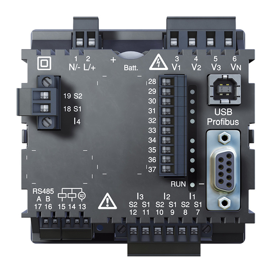
000 if the device is used in a Profibus-System. The baud rate in a Profibus system is de- tected automatically and must NOT be set Fig. UMG 96RM-P with D-sub receptacle for Profibus via the address 001! (View on rear). - Page 38 UMG 96RM-P/-CBM Connection of the bus wiring The inbound bus wiring is connected to terminals 1A UMG 96RM-P Profibus connector (external) Profibus and 1B of the Profibus connector. The continuing bus Termination resistors wiring for the next device in line should be connected to terminals 2A and 2B.
-
Page 39: Digital Outputs
UMG 96RM-P/-CBM Digital outputs The UMG 96RM-P and UMG 96RM-CBM have 6 digital outputs, whereby these are split into two groups of 2 and 4 outputs (see illustration on the right). Group 2 Digital outputs, Group 1 • The status indicator appears on the display at K1 or •... - Page 40 Functions for the digital outputs can be adjusted clearly in the GridVis software provided in the scope of deliverables. A connection between the UMG 96RM-P/ When using the digital outputs as pulse outputs the auxiliary voltage (DC) must -CBM and the PC via an interface is re- quired for the use of the GridVis software.
- Page 41 UMG 96RM-P/-CBM DC connection example External UMG 96RM-P/-CBM auxiliary voltage 24V DC Digital Ouput 1 Digital Ouput 2 Digital Ouput 3 Digital Ouput 4 Digital Ouput 5 Fig. Example for two Digital Ouput 6 relays connected to the digital outputs...
-
Page 42: Digital Inputs
UMG 96RM-P/-CBM Digital inputs External auxiliary voltage 24V DC The UMG 96RM-P and UMG96RM-CBM have 4 digital inputs, each of which can have a signal transducer UMG 96RM-P/-CBM connected. Digital inputs 1-4 On a digital input an input signal is detected if a voltage... - Page 43 UMG 96RM-P/-CBM S0 pulse input External auxiliary voltage 24V DC You can connect an S0 pulse transducer per DIN EN62053-31 to any digital input. UMG 96RM-P/-CBM Digital inputs 1-4 This requires an auxiliary voltage with an output voltage in the range 20 .. 28V DC and a resistor of 1.5kOhm.
-
Page 44: Led Status Bar
- independent of whether there is a connection on the interface. Profibus (only -P model) Profibus (only UMG 96RM-P variant) Fig. LED status bar for inputs and outputs The LED associated with the Profibus provides... - Page 45 UMG 96RM-P/-CBM Profibus status LED Flashing frequency Green Status Illuminates steadily Still no contact with PLC Slowly (approx. 1x per sec.) Fault in the configuration data Very slowly (approx. 1x per 2 sec.) Fault with data exchange Illuminates steadily Data exchange with the PLC Quickly (approx.
-
Page 46: Operation
UMG 96RM-P/-CBM Operation programmed, the user arrives directly in the first The UMG 96RM-P/-CBM is operated using buttons 1 and 2. Measured values and programming data appears programming menu. Programming mode is indicated by the text “PRG” on the display. - Page 47 UMG 96RM-P/-CBM Maximum value, HT/import Minimum value, NT/export Mean value Programming mode Sum measurement Phase conductor- Phase conductor Password CT: Current transformer VT: Voltage transformer K1: Output 1 K2: Output 2 Button 2 Export Button 1...
-
Page 48: Parameters And Measured Values
UMG 96RM-P/-CBM Parameters and measured values Example of the parameter display All parameters necessary for operating the UMG On the UMG 96RM-P/-CBM 96RM-P/-CBM, e.g. the current transformer data, and display value “001” a selection of frequently required measured values are is shown as the content stored in the table. -
Page 49: Button Functions
UMG 96RM-P/-CBM Button functions Display mode Programming mode Change mode Change mode Password simultaneous simultaneous Browse Browse Programming short menu 1 short Measured Programming values 1a menu 2 long Programming Measured Measured menu 3 long values 2a values 2b long... -
Page 50: Configuration
The level of supply voltage for the UMG 96RM-P/-CBM can be found on the nameplate. The adjustable value 0 for the primary current transformer does not produce... - Page 51 UMG 96RM-P/-CBM Current and voltage transformers The transformer ratios for each of the three current and voltage measurement inputs can be individually programmed in the Gri- dVis software included in the scope of delivery. Only the transformer ratio of the...
-
Page 52: Programming Current Transformers
UMG 96RM-P/-CBM Programming current transformers Switching to programming mode Current transformer secondary current input • Simultaneously press buttons 1 and 2 in order • Only 1 A or 5 A can be set as the secondary current. to switch to programming mode. If a user password •... -
Page 53: Programming Voltage Transformers
UMG 96RM-P/-CBM Programming voltage transformers Current transformer, primary • Switch to the programming mode as described. The Programming mode symbols for the programming mode (PRG) and for the Units display current transformer (CT) appear. • Use button 2 to switch to the voltage transformer Current transformer, secondary setting. -
Page 54: Programming Parameters
UMG 96RM-P/-CBM Programming parameters Fig. Password request If a password was set, Switching to programming mode it can be entered using • Switch to the programming mode as described. The buttons 1 and 2. symbols for the programming mode (PRG) and for the current transformer (CT) appear. - Page 55 UMG 96RM-P/-CBM Device address (addr. 000) Mean value If several devices are connected to one another Mean values are formed over an adjustable period via the RS485 interface, a master device can only for the current, voltage and power measured values.
- Page 56 UMG 96RM-P/-CBM Averaging method Minimum and maximum values After the set averaging time, the exponential averaging All measured values are measured and calculated every method used achieves at least 95% of the measured 10/12 periods. Minimum and maximum values are deter- value.
- Page 57 UMG 96RM-P/-CBM Mains frequency (addr. 034) For automatic ascertainment of the mains frequency, an Adjustment range: 0, 45 .. 65 L1-N voltage larger than 10Veff must be applied to the automatic frequency determination. voltage measurement input V1. The mains frequency is determined from the measurement voltage.
- Page 58 UMG 96RM-P/-CBM Energy meter Reading the active energy The UMG 96RM-P/-CBM has energy meters for active Total active energy energy, reactive energy and apparent energy. The active energy in this example is: 12 345 678 kWh The active energy in this...
- Page 59 Harmonics are the integer multiple of a mains frequency. THD is the ratio of the root mean square value of The voltage mains frequency for the UMG 96RM-P/ harmonics to the root mean square value of the mains -CBM must be in the range between 45 and 65 Hz. The frequency.
- Page 60 If no button is pressed for about 60 seconds, the device After return of the power supply, the UMG 96RM-P/ switches to the measured value relay and the measured -CBM shows the first measured value panel from the values from the selected display change profile current display profile.
- Page 61 Fig. Display of the profile setting in the GridVis play profiles can also be programmed. software. A connection between the UMG 96RM-P/ -CBM and the PC via the serial interface (RS485) is required for using the GridVis soft- ware. This requires an interface converter RS485/232, item no.
- Page 62 GridVis PC software. Clearing the energy meters means this To do this, connect the UMG 96RM-P/-CBM to the PC data in the device is gone. via a suitable interface. More information can be found In order to avoid possible data loss, in the help section of GridVis.
- Page 63 The phase sequence at the voltage measurement inputs 0 = characters are very light is checked and displayed in the UMG 96RM-P/-CBM. 9 = characters are very dark A movement of the character string in the clockwise direction means a "right rotation"...
- Page 64 Time recording The operation backlight is activated by pushing the ap- propriate button, or with a restart. The UMG 96RM-P/-CBM records the operating hours and the total running time of each comparator Standby backlight (addr. 747) This backlight is activated after an adjustable period of •...
- Page 65 Operating hours meter Serial number (addr. 754) The operating hours meter measures the time for which The serial number shown by UMG 96RM-P/-CBM the UMG 96RM-P/-CBM records and displays measured has 6 digits and is part of the serial number displayed values.
-
Page 66: Recordings
• Apparent Power Sum L1-L3 2 recordings are preconfigured in the default factory • cos phi(math.) L1 setting of the UMG 96RM-P and UMG 96RM-CBM. • cos phi(math.) L2 Recordings are adjusted and extended via the software • cos phi(math.) L3 “GridVis”. - Page 67 UMG 96RM-P/-CBM...
-
Page 68: Commissioning
Applying the supply voltage A and ../5 A current transformers. Only AC currents and not DC currents can be measured • The level of supply voltage for the UMG 96RM-P/ via the current measurement inputs. -CBM can be found on the nameplate. -
Page 69: Rotation Field Direction
The UMG 96RM- short-circuited at the secondary terminals. The apparent P/-CBM must only show one rating in the phase with power shown by the UMG 96RM-P/-CBM must then be the non-short-circuited current transformer input. If this zero in this phase. -
Page 70: Check The Sum Power Ratings
If all voltages, currents and power ratings for the respective phase conductor are correctly displayed, the sum power ratings measured by the UMG 96RM-P/ -CBM must also be correct. For confirmation, the sum power ratings measured by the UMG 96RM-P/-CBM should be compared with the energy of the active and reactive power meters at the power feed. -
Page 71: Rs485 Interface
23 (17Hex) Read/Write 4X Registers The sequence of bytes is high before low byte (Motorola format). Transmission parameters: Data bits: 8 Parity: None Stop bits (UMG 96RM-P/-CBM): 2 External stop bits: 1 or 2 Number formats: short 16 bit (-2 .. 2 float... - Page 72 UMG 96RM-P/-CBM Example: Reading the L1-N voltage The "response" from the UMG 96RM-P/-CBM can then The L1-N voltage is stored in the measured value list appear as follows: under the address 19000. The L1-N voltage is stored in INT format.
- Page 73 UMG 96RM-P/-CBM...
-
Page 74: Installation Of Usb Driver
• Linux system: 96RM-P/-CBM, as a minimum. Follow the instructions in the Readme file in • Connect the UMG 96RM-P/-CBM to a suitable the UMG96RM/USB drivers/Linux folder. USB interface on the computer with the USB cable • Connect the power supply voltage for the UMG provided. - Page 75 USB Universal Controller. • Start the GridVis software and integrate the UMG 96RM-P/-CBM with the assistant (New file...). After selecting the connection type (USB) and the interface of the COM port (COMx, see above) the USB...
-
Page 76: Profibus Interface (Only Umg 96Rm-P)
UMG 96RM-P/-CBM Profibus interface (only UMG 96RM-P) Activate outputs/tariffs via Profibus Profibus profiles To set the outputs or the tariffs an appropriate profile must be selected. Alongside the 1st byte used for the profile A Profibus profile contains the data to be exchanged selection three further bytes can be used to: between a UMG and a PLC. - Page 77 UMG 96RM-P/-CBM Control tariffs (4th byte): Example: Bit: Output 1-3 set Setting or clearing bits 0 to 6 of byte 4 enables a selection of energy meters for the tariff set. Each tariff can have Unused up to 7 energy meters allocated to it.
- Page 78 UMG 96RM-P/-CBM Deactivate energy meters / tariffs via Profibus If energy meters are assigned to a tariff then these Byte 4: Deactivating energy meters can be deactivated via byte 3 and byte 4 (cf. activate Bit: tariffs via Profibus). Here the selection of the desired...
- Page 79 Profibus profile number 8. The 1st byte should be set to the profile number 8 (dec.) and sent to the UMG 96RM-P. The UMG 96RM-P then delivers the profile number 8 and the measured values set in profile 8 back. Bit:...
- Page 80 4th byte = Select energy meter PLC process input box 1st byte = Return signal from the profile number Profile number Measurement values 2nd byte = Requested by UMG 96RM-P Data • • Fig. Block diagram for data exchange between PLC and UMG 96RM-P.
- Page 81 UMG 96RM-P. The GSD file is required by the configuration program of the PLC. The device master file for the UMG 96RM-P has the filename „96RM0D44.GSD“ and is included on the data carrier as part of the scope of deliverables.
- Page 82 Float in the scope of deliverables. A connection Reactive power fundamental oscillation Float harmonic sum L1..L3 between the UMG 96RM-P and the PC via THD voltage L1 Float an interface is required for the use of the THD voltage L2 Float GridVis software.
- Page 83 Apparent power L2 Float spect the transformer ratio. Measured values Apparent power L3 Float in floating point format contain the transfor- Apparent power sum L1..L3 Float mer ratio: value in the UMG 96RM-P display = transformer ratio x value PLC x solution...
-
Page 84: Digital Outputs
UMG 96RM-P/-CBM Digital outputs The UMG 96RM-P and UMG 96RM-CBM have 6 digital outputs, whereby these are split into two groups of 2 and 4 outputs (see illustration on the right). . The User can allocate different functions to the digital... - Page 85 UMG 96RM-P/-CBM Digital outputs 1 and 2 — Status displays The status of the switching outputs of group 1 is indica- Since the indication is updated once per ted by circular symbols in the display of the UMG 96RM- second, faster status changes of the out- P/-CBM.
-
Page 86: Impulse Output
UMG 96RM-P/-CBM Impulse output The digital outputs can be used for the output of pulses for the computation of power consumption. For this pur- pose, a pulse of defined length is applied on the output after reaching a certain, adjustable amount of power. - Page 87 UMG 96RM-P/-CBM Pulse length (addr. 106) The pulse length applies for both pulse outputs and is Due to the minimum pulse length and minimum pulse permanently fixed via parameter address 106. pause, the values in the table are for the maximum number of pulses per hour.
- Page 88 UMG 96RM-P/-CBM Pulse value (addr. 102, 104) The pulse value specifies how much energy (Wh or varh) should correspond to a pulse. The pulse value is determined by the maximum connected load and the maximum number of pulses per hour.
- Page 89 UMG 96RM-P/-CBM Determining the pulse value External 230 V AC operating voltage Setting the pulse length 24 V DC Set the pulse length according to the requirements of the connected pulse receiver. UMG 96RM-P/-CBM For a pulse length of 30 ms, for example, the UMG 96RM-...
-
Page 90: Comparators And Monitoring Threshold Values
UMG 96RM-P/-CBM Comparators and monitoring threshold values Six comparator groups (1 - 6) and three comparators per group (A – C) can be selected in order to monitor/control the thresholds. The results of the comparators A to J can be linked with AND or OR operators. - Page 91 UMG 96RM-P/-CBM...
-
Page 92: Service And Maintenance
Disposal Calibration intervals The UMG 96RM-P/-CBM can be reused or recycled as electronic scrap in accordance with the legal provi- It is recommended to have a new calibration carried out sions. The permanently installed lithium battery must by the manufacturer or an accredited laboratory every be disposed of separately. -
Page 93: Firmware Update
UMG 96RM-P/-CBM Firmware update Battery If the device is connected to a computer via Ethernet, The internal clock is fed from the supply voltage. then the device firmware can be updated via the GridVis If the supply voltage fails then the clock is powered software. -
Page 94: Battery Monitoring Function
UMG 96RM-P/-CBM Battery monitoring function Status Status description • Battery capacity is <85% The device indicates the condition of the battery via • Operator confirmation required the "EEE" symbol followed by "bAt" and the status num- • Message appears weekly after confir- ber. -
Page 95: Replacing The Battery
UMG 96RM-P/-CBM Replacing the battery If the battery capacity is shown as < 75 %, we recom- mend that the battery be replaced. Procedure 1. Disconnect system and device from power supply before beginning work. 2. Discharge any electrostatic charge in your body, e. g. -
Page 96: Error Messages
EEPROM. The device The three-digit error number is composed of the error must be sent to the manu- description and (if detectable by the UMG 96RM-P/-CBM) facturer for inspection. one or more error causes. - Page 97 The UMG 96RM-P/-CBM can usually determine the acknowledged with buttons 1 or 2. The measured values cause of an internal error and then report it with the continue to be recorded and displayed. This error is re- following error code.
- Page 98 UMG 96RM-P/-CBM Overranges Examples Overranges are displayed as long as they exist and can- not be acknowledged. An overrange exists if at least one of the voltage or current measurement inputs lies out- side their specified measuring range. A = current path The "upwards"...
- Page 99 UMG 96RM-P/-CBM Parameter overrange A detailed description of the error is coded in the param- eter overrange (Addr. 600) in the following format: F F F F F F F F Phase 1: Phase 2: Phase 3: Example: Error in phase 2 in the current path:...
- Page 100 UMG 96RM-P/-CBM Procedure in the event of faults Possible fault Cause Remedy No display External fusing for the power supply voltage has Replace fuse. tripped. No current display Measurement voltage is not connected. Connect the measuring-circuit voltage. Measurement current is not connected.
- Page 101 UMG 96RM-P/-CBM Possible fault Cause Remedy Effective power too large or too The programmed current transformer transfor- Read out and program the current transformer small. mation ratio is incorrect. transformation ratio at the current transformer The current path is assigned to the wrong Check connection and correct if necessary.
-
Page 102: Technical Data
UMG 96RM-P/-CBM Technical data General Net weight (with attached connectors) approx. 358g Packaging weight (including accessories) approx. 790g Battery Lithium battery CR2032, 3V (approval i.a.w. UL 1642) Service life of the backlight 40000h (after this period of time the background lighting effici- ency will reduce by approx. - Page 103 UMG 96RM-P/-CBM Supply voltage Installation overvoltage category 300V CAT II Protection of the power supply (fuse) 6 A, type C (approved by UL/IEC) Nominal range 20V - 250V (45..65Hz) or DC 20V - 300V Working area +-10% from the nominal range Power consumption max.
- Page 104 UMG 96RM-P/-CBM Digital inputs 4 optional digital outputs, semiconductor relays, not short-circuit proof. Maximum counter frequency 20Hz Input signal present 18V .. 28V DC (typical 4mA) Input signal not present 0 .. 5V DC, current less than 0.5A Cable lengths (digital inputs and outputs)
- Page 105 Mains frequency 45Hz .. 65Hz - Resolution 0.01Hz The UMG 96RM-P/-CBM can only determine exact measured values if a measurement-current voltage greater than 10 Veff or a L-L voltage larger than 18 Veff is applied to the voltage measurement input L1.
- Page 106 UMG 96RM-P/-CBM Current measurement I1 - I4 Rated current Measurement range 0 .. 6A Crest factor 1.98 Resolution 0.1mA (Display 0.01A) Overvoltage category 300V CAT II Measurement surge voltage Power consumption ca. 0.2 VA (Ri=5mOhm) Overload for 1 sec. 120A (sinusoidal) Sampling frequency 21.33kHz (50Hz), 25.6 kHz (60Hz) per measurement channel...
- Page 107 UMG 96RM-P/-CBM...
-
Page 108: Parameters Of Functions
UMG 96RM-P/-CBM Parameters of functions Function Symbol Accuracy class Metering range Display range Total real power (IEC61557-12) 0 .. 5.4 kW 0 W .. 999 GW * Total reactive power QA, Qv (IEC61557-12) 0 .. 5.4 kvar 0 varh .. 999 Gvar *... - Page 109 UMG 96RM-P/-CBM Function Symbol Accuracy class Metering range Display range Current harmonics Class 1 (IEC61000-4-7) up to 2.5 kHz 0 A .. 999 kA THD of the current THDi (IEC61557-12) up to 2.5 kHz 0 % .. 999 % THD of the current...
-
Page 110: Table 1 - Parameter List
A complete overview of the parameters and settings that are necessary for proper operation of the measured values as well as explanations UMG 96RM-P/-CBM, such as current transformers and regarding the selected measured values device addresses. The values in the parameter list can is filed in the document “Modbus Address... - Page 111 UMG 96RM-P/-CBM Address Format RD/WR Unit Note Adjustment Range Default FLOAT RD/WR Voltage transformer V2, prim. 0..1000000 FLOAT RD/WR Voltage transformer V2, sec. 100, 400 FLOAT RD/WR Current transformer I3, primary 0..1000000 FLOAT RD/WR Current transformer I3, sec. 1..5 FLOAT RD/WR Voltage transformer V3, prim.
- Page 112 UMG 96RM-P/-CBM Address Format RD/WR Unit Note Adjustment Range Default SHORT RD/WR Password 0 .. 999 0 (no password) SHORT RD/WR Address of the measured value, Digital output 1 0..32000 SHORT RD/WR Address of the measured value, Digital output 2 0..32000...
- Page 113 UMG 96RM-P/-CBM Address Format RD/WR Unit Note Adjustment Range Default SHORT RD/WR Year 0..99 SHORT RD/WR Month 0..12 SHORT RD/WR 0..31 SHORT RD/WR Hour 0..24 SHORT RD/WR Minute 0..59 SHORT RD/WR Second 0..59 UINT RD/WR Metering range exceedance 0..0xFFFFFFFF SHORT...
-
Page 114: Table 2 - Modbus Address List
UMG 96RM-P/-CBM Table 2 - Modbus address list (frequently used measured values) The addresses contained in the descripti- A complete overview of the parameters and on can be adjusted directly on the device measured values as well as explanations in the range from 0 to 800. - Page 115 UMG 96RM-P/-CBM Modbus Address Address Above display Format RD/WR Unit Note 19032 float Apparent power S L3 19034 float Sum; Ssum3=S1+S2+S3 19036 float Fund. reactive power (mains frequ.) Q L1 19038 float Fund. reactive power (mains frequ.) Q L2 19040 float Fund.
- Page 116 UMG 96RM-P/-CBM Modbus Address Address Above display Format RD/WR Unit Note 19094 float varh Reactive energy, inductive, L1 19096 float varh Reactive energy, inductive, L2 19098 float varh Reactive energy, inductive, L3 19100 float varh Reactive energy L1..L3, ind. 19102...
-
Page 117: Number Formats
UMG 96RM-P/-CBM Number formats Type Size Minimum Maximum short 16 bit ushort 16 bit 32 bit uint 32 bit float 32 bit IEEE 754 IEEE 754 Notes on saving measurement values and configuration data: • The following measurement values are saved at least every 5 minutes: •... -
Page 118: Dimension Diagrams
UMG 96RM-P/-CBM Dimension diagrams All dimensions in mm. Rear view of UMG 96RM-P Side view of UMG 96RM-P with USB and Profibus connectors inserted ca. 108 (depth without connector) - Page 119 UMG 96RM-P/-CBM Rear view of UMG 96RM-CBM Side view of UMG 96RM-CBM with USB connector inserted ca. 108 (depth without connector)
- Page 120 UMG 96RM-P/-CBM Cutout dimensions +0,8...
-
Page 121: Overview Of Measured Value Displays
UMG 96RM-P/-CBM Overview of measured value displays Measured values Mean values Maximum values Minimum values L1-N voltage L1-N voltage L1-N voltage L1-N voltage L2-N voltage L2-N voltage L2-N voltage L2-N voltage L3-N voltage L3-N voltage L3-N voltage L3-N voltage Measured values... - Page 122 UMG 96RM-P/-CBM Measured value Mean value Maximum value Apparent power Apparent power Apparent power Measured values Mean values Maximum values (ind) L1 reactive power L1 reactive power L1 reactive power L2 reactive power L2 reactive power L2 reactive power L3 reactive power...
- Page 123 UMG 96RM-P/-CBM Measured value L1 cos(phi) L2 cos(phi) L3 cos(phi) Measured value Mean value Sum of cos(phi) Sum of cos(phi) Measured value Frequency L1 Rotation field display Measured value Measured value Measured value Measured value Measured value Measured value Measured value...
- Page 124 UMG 96RM-P/-CBM Measured value Measured value Measured value 1st. harmonic 3rd. harmonic 15th. harmonic U L2 U L2 U L2 Measured value Measured value Measured value 1st. harmonic 3rd. harmonic 15th. harmonic U L3 U L3 U L3 Measured value...
- Page 125 UMG 96RM-P/-CBM Maximum value Maximum value Maximum value 1st. harmonic 3rd. harmonic 15th. harmonic U L3 U L3 U L3 Maximum value Maximum value Maximum value 1st. harmonic 3rd. harmonic 15th. harmonic I L1 I L1 I L1 Maximum value...
-
Page 126: Declaration Of Conformity
UMG 96RM-P/-CBM Declaration of conformity The product fulfils the following EC Directives: 2004/108/EG Electromagnetic compatibility of electrical equipment. 2006/95/EG Electrical equipment for use within certain voltage limits. Considered standards Noise immunity IEC/EN 61326-1:2013 Klasse A: Class A: Industrial environment IEC/EN 61000-4-2:2009... -
Page 127: Connection Example
UMG 96RM-P/-CBM Connection example 28 29 Digital outputs Digital inputs RS485 UMG 96RM-P/CBM Auxiliary voltage Measuring voltage Measuring currrent N/- L/+ 19 18 UL / IEC approved overcurrent protection system (6A type C) UL / IEC approved overcurrent protection system (10A type C) -
Page 128: Basic Functions Quick Guide
UMG 96RM-P/-CBM Basic functions quick guide Adjusting current transformer, primary current Adjusting the current transformer Display Programming mode Switch to the programming mode: • Press button 1 and 2 simultaneously for around 1 se- Adjusting current transfor- mer, secondary current cond to switch to the programming mode.
Need help?
Do you have a question about the UMG 96RM-P and is the answer not in the manual?
Questions and answers