Octane Fitness XR6000 Assembly Instructions
Hide thumbs
Also See for XR6000:
- Operation manual (24 pages) ,
- Manual & setup instructions (12 pages) ,
- Assembly and operation instructions manual (8 pages)
Table of Contents
Advertisement
Quick Links
Arm Pivot Cover–Large
Box Contents
(Right and Left)
113185-001
Console Mast
112738-001
Arm Pivot Cover–Small
(Right and Left)
Base
113182-001
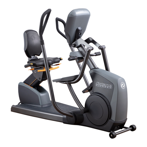
(xR6000 shown)
Standard Console Box Contents
Standard Console
(Front and Back)
8020168
Time
Calories
Distance
Speed
HR%
HR
Level
PRESS TO ACTIVATE
Fast
Push Arms Pull Arms
A built-in personal trainer to motivate you with intense intervals
Higher resistance intervals isolating arms, shoulders and chest
Legs Only
Resistance
+
Challenging intervals isolating legs for power and toning
Narrow Grip Wide Grip
Reverse
Quick Start
PAUSE
CLEAR
OCTANE
MMA
Program
Enter
30:30
Workout
Level
FAVORITES
Read and understand the "Product Safety Information" manual
before assembly.
Remove all loose parts from packaging; use handle to
lift rear of base and gently roll unit off
shipping pallet.
Use 6mm hex wrench to remove bolt and
washer from right side of seat back axle;
slide axle out user left side.
Position seat back; insert axle from left side through seat back
bracket, aligning flat sides of axle and hole. Align washer and
bolt with axle; tighten with 6mm hex wrench to 19 ft-lb.
Insert spacer B-2 (quantity 1) through hole in damper. Tilt seat
and align damper/spacer in seat bracket. Insert screw B-1
(quantity 1) through bracket and damper/spacer;
tighten with 5mm hex wrench to 7 ft-lb.
Test seat height and tilt adjustments to verify function of locking
mechanisms (not shown). (On xR6000s, also test swivel mechanism.)
C
Install Console
F-2
and mast cover, C-SAFE
Power for
Accessories
(unused)
Power
(white, 4-pin)
Standard Console
Handlebar Control
(white, 7-pin)
Console to Base
(white, 14-pin)
C-SAFE
(Connect from mast
cover in Step
USA & Canada
888-OCTANE4
113201-001 REV E Page 1/2
©2020 Octane Fitness. All rights reserved.
Assembly Instructions
Foot Pedals
(Right and Left)
113183-001
111660-001
116661-001
113184-001
Side Step (2)
(xR6000s only)
113208-001
Hardware Pack
Tools Required:
110622-001
#2 Phillips Screwdriver
C-1 (10)
100780-001
#2 Phillips
Information Packet (attached to console)
110601-001 Notice to Installers
111289-001 xR6000 Console Guide & Setup
Instructions–Standard Console
104198-001 Warranty
101315-001 Registration Card
Separate console back from console front; set console back aside (not shown).
Standard
Connect the C-SAFE cable from the mast cover to the console (cable not
Console
shown). Note: If you are installing a 900 MHz accessory, remove and
discard the C-SAFE cable.
Connect heart rate cable attached to heart rate board on console back
to heart rate cable from mast (black, 6-pin connector).
Make additional cable connections from mast to back of console:
Standard Console:
F-2
Smart Console:
Routing loose cables to user front side of mast brackets, attach console front to
top of mast with C-1 (quantity 4); tighten using Phillips #2 screwdriver. Remove
screw securing mast cover to mast; retain screw. (If C-SAFE cable is in use,
let mast cover hang from cable.)
For Smart console only: Install power switch; connect cable and power.
(Install back cover
a. Remove rubber plug from mast cover (not shown).
cable not shown)
b. Route two-connector end of switch cable (pre-connected to console) through the
opening where plug was removed. Attach connectors to tabs on switch
(either connector can go on either tab).
c. Press switch fully into opening of mast cover; let mast cover hang
from cables.
Audio for
d. Connect power cord and power supply. Plug into base of unit
Accessories
and wall socket to verify power to console. Unplug from wall socket before
(unused)
continuing to step D.
Reserved for
Software Field Update
(black)
Reserved
6 - c
(unused)
Console Ground
(metal; green wire from mast)
LAN
)
(RS-232)
octanefitness.com
Moving Handlebars
(Right and Left)
112509-001
112508-001
Seat Back
112832-001
Foot Rest/Accessory Tray
112824-001
Hardware Pack
112844-001
(not shown)
Information Packet
113201-001 Assembly
107786-001 Safety Instructions
Smart Console
(Front and Back)
8019479
Use #2 Phillips screwdriver to remove two screws
securing front and rear top shrouds and mast boot. Set
A
screws, shrouds, and mast boot aside (not shown).
Install Seat
Remove twist tie securing cable bundle; tip mast
upside down and route cables through hole in
bottom of mast to top of mast.
Slide mast over screws on base; insert screw B-3
(quantity 2) into holes in front of mast plate, tighten
with 6mm hex wrench.
Insert screw B-3 (quantity 2) into holes in top of
mast plate. Use 6mm hex wrench to tighten
all 6 screws to 30 ft-lb.
Align bottom of front top shroud with base, then tip up
into position. Position rear top shroud and mast boot,
then secure both top shroud pieces using #2 Phillips
screwdriver and two screws removed in step 1.
power,
handlebars,
base,
LAN,
ground
power,
handlebars,
base,
(leave ground unconnected)
6 - d
Questions?
Hardware Pack
B -1 (1)
B -2 (1)
B -3 (4)
B -4 (2)
112734-001
101295-001
109989-001
112223-001
6mm
13mm
6mm
B -8(4)
B -9 (4)
B -10 (2)
B -11 (4)
101277-001
105717-001
100780-001
8022048
#2 Phillips
5mm
5mm Hex (1)
103083-001
Tools Required:
#2 Phillips screwdriver
5mm hex wrench (provided)
Flat head screwdriver
6mm hex wrench (provided)
Smart Console Box Contents
Hardware Pack
110622-001
C-1 (10)
100780-001
#2 Phillips
Power Switch
Information Packet (attached to console)
111032-001
110601-001 Notice to Installers
111768-001 Console Guide & Set-up Instructions–
Tools Required:
104198-001 Warranty
#2 Phillips Screwdriver
101315-001 Registration Card
LAN
Power
(white, 4-pin)
LAN
(RS-232)
(on Android board
underneath)
Handlebar Control
(white, 7-pin)
Latin America/Asian Pacific
B -5 (4)
B -6 (2)
B -6 (2)
B -7 (2)
104757-001
103743-001
103743-001
103393-001
13mm
B -12 (2)
B -13 (2)
112736-001
113194-001
6mm
6mm Hex (1)
8008949
13mm wrench
17mm wrench
Rubber mallet
(optional)
Power Supply
112584-001
(may be boxed separately)
Power Cord
107658-001
(may be boxed separately)
Smart Console
B
cables
Install
through
here
Mast
Smart
Console
F-2
F-2
(Install back cover
and mast cover, C-SAFE
cable and power switch
cable not shown)
Smart Console
Power for
Accessories
(unused)
(unused)
(unused)
C-SAFE
Console to Base
(Connect from mast
(unused)
(white, 14-pin)
cover in Step
)
(unused)
(unused)
(unused)
001-763-757-2662
Europe/Middle East/Africa
31-10-2662412
Advertisement
Table of Contents

Related Manuals for Octane Fitness XR6000


Summary of Contents for Octane Fitness XR6000
- Page 1 Information Packet (attached to console) 111032-001 110601-001 Notice to Installers 110601-001 Notice to Installers 111289-001 xR6000 Console Guide & Setup 111768-001 Console Guide & Set-up Instructions– Instructions–Standard Console Smart Console Tools Required: 104198-001 Warranty 104198-001 Warranty #2 Phillips Screwdriver...
- Page 2 Carefully tip unit away from you and push side step under rail of unit. Lower unit onto side step channel. Repeat for second side step. Questions? USA & Canada Latin America/Asian Pacific 888-OCTANE4 001-763-757-2662 octanefitness.com Europe/Middle East/Africa 113201-001 REV E Page 2/2 31-10-2662412 ©2020 Octane Fitness. All rights reserved.
Need help?
Do you have a question about the XR6000 and is the answer not in the manual?
Questions and answers