Advertisement
Quick Links
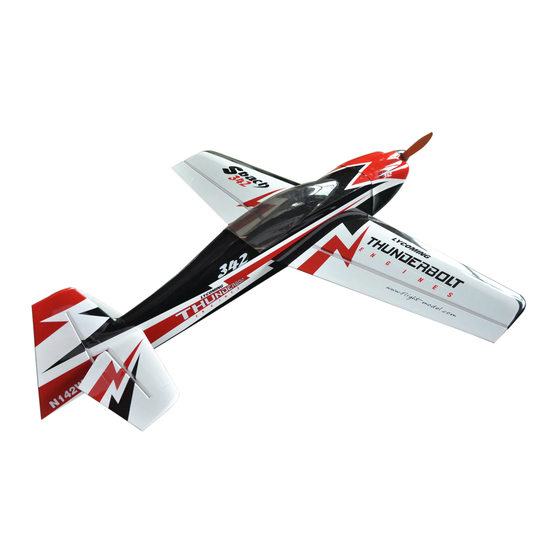
Sbach – 1,2m 3D/aerobatic EPP model
Building instructions
Please refer to the Diagram sheet
Diagrams A, B
Press 2 carbon strips (1x3x1000 mm) into the grooves in the sides of the fuselage central part (the
„backbone"). Position the backbone on your workbench on its side, gently press if necessary and make
sure that the sides are perfectly straight. Apply thin CA glue over the carbon strips and saw off their
overhanging ends.
Diagram C
Use thin or medium CA to attach the wing halves to the backbone. Note the little tabs that should help
you position the wing halves correctly. (put some down pressure on the thickest part of the root of the
wing first to set the wing at 0° incidence). Caution! The backbone should be in inverted position, i.e.
the elevator cutout facing down and the wings should be attached with their bottom side up! If you get
this wrong, your elevator will not fit into the fuselage correctly.
Diagram D
Locate two carbon strips (1x5x1000 mm). Use sharp hobby knife to cut shallow (5mm) slits into the
upper and lower surface of the wing as indicated. Press the two carbon rods into the slits. Make sure
that the wing is perfectly straight (press gently down on the workbench) and apply thin CA glue over
the carbonstrips. Cut two shallow slits into the backbone according to the part 2 of diagram D.
Diagram E
Cut shallow slits into the elevator upper and lower surface as indicated. Press in two carbon strips.
Make sure that the elevator is straight and apply thin CA glue over the carbon strips.
Diagram F
Glue (using thin or medium CA) the canopy (made of black EPP) into place. Use sharp hobby knife to
separate the fuselage upper and lower parts, cutting through the center of the little tabs.
Diagram G
Put the backbone on your workbench in inverted position (the stabilizer cutout is again facing down).
Assemble together the landing gear plate and the stirrups. Glue the LG plate to the bottom edge of the
slot in stirrups according to the diagram. Use thin CA to glue the landing gear mount to the backbone.
Diagram H
Connect the lower fuselage part to the bacbone using thin or medium CA or contact glue. Install the
stab/elevator into the assembly using thin or medium CA (check its proper alignment first). Use
medium CA to glue anti-torsion reinforcements.
Diagram I
Drill holes into the landing gear as indicated.
Diagram J
Slide landing gear legs into the stirrups. Due to manufacturing tolerances you may need to trim slots in
stirrups. Use two wood-screws (2,9x6mm) to screw the LG to the LG mount. To remove the LG you
can just slightly loosen the screws. Assemble the landing gear as indicated. Gluing the EPP wheel
pants to their mounting tabs is the last step of the LG assembly.
Diagram K
Now is the convenient time to install aileron servos. Cut appropriate slots into the wing lower surface
using sharp hobby knife. Make the slot somewhat smaller, for a tight fit. Use hot glue or thick CA to
install the servos. Cut into the ailerons and press in the aileron control horns. Make sure your servos
are centered (with zero trim). Glue the control horn into the aileron.
Advertisement

Related Manuals for RC Factory SBACH 342


Summary of Contents for RC Factory SBACH 342
- Page 1 Sbach – 1,2m 3D/aerobatic EPP model Building instructions Please refer to the Diagram sheet Diagrams A, B Press 2 carbon strips (1x3x1000 mm) into the grooves in the sides of the fuselage central part (the „backbone“). Position the backbone on your workbench on its side, gently press if necessary and make sure that the sides are perfectly straight.
- Page 2 Use the included pushrods (carbon rod 1,8x50 mm) with ball links on both ends. Screw ball links to the servo arm and control horn using M1,6x4 mm screws. Trim the lenght of carbon rod to sleeve it into ball links about 5mm deep. Check neutral position of servo and aileron and glue together pushrod and ball links using thin CA.
- Page 3 For clean rolls, without any coupling to yaw, you may want to play with aileron differential (different up and down deflection of ailerons). Have fun! Your RC Factory team. Technical specs: Wingspan 1220 mm...
- Page 4 Sbach 1.2m V2.0 Kit contains: *Carbon rods and strips: *Fuselage *Wings - 2x 1x3x1000 - fuselage *Cannopy *Landing gear - 2x 1x5x1000 - wing *Backbone *Wheell pants - 1x tube 2/1x500 - elevator pushrod *Elevator *Anti-torsion reinforcements(2x) - 1x 1x5x245mm - elevator *Rudder *Bag with hardware - 1x 1x3x245mm - elevator...
- Page 5 carbon 1x5x1000 mm carbon carbon 1x3x245 mm 1x3x100 mm 1x5x245mm...
- Page 6 washer 3mm socked head M3x15mm wood screw 2.9x6mm nut M3 M2x5 M2x8 M2x5 110mm M2x5...