Table of Contents
Troubleshooting

Related Manuals for SWF SWF E- Series


Summary of Contents for SWF SWF E- Series
- Page 1 Embroidery Machine (New Compact Type) SWF/E- Series M M M M E E - - 0 0 6 6 0 0 3 3 1 1 0 0 S S U U N N S S T T A A R R P P R R E E C C I I S S I I O O N N C C O O . . , , L L T T D D . .
- Page 2 1. THIS IS AN INSTRUCTION FOR SAFE USE OF AUTOMATIC EMBROIDERY MACHINES. READ THOROUGHLY BEFORE USE. 2. CONTENTS IN THIS INSTRUCTION MAY CHANGE, WITHOUT PRIOR NOTICE, FOR IMPROVEMENT OF MACHINE QUALITY AND THUS MAY NOT CORRESPOND TO THE MACHINE YOU PURCHASED.
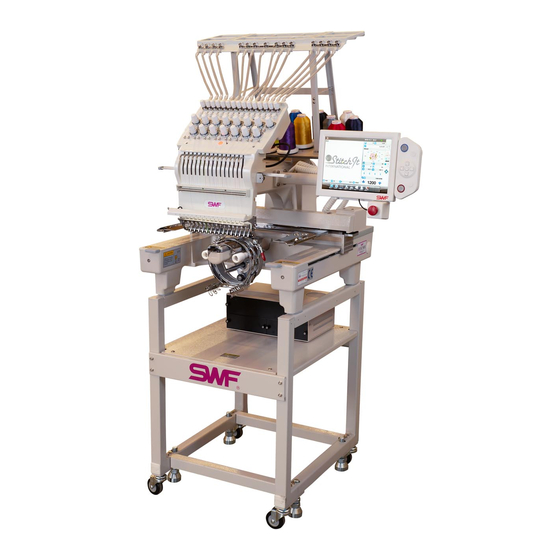
- Page 3 SWF/E-T601C or SWF/E-T901C SWF/E-T1201C or SWF/E-T1501C WELCOME to the SWF FAMILY !! OUR SUCCESS IS IMPORTANT TO US. We want to be your partner in business where you machine is concerned. Your machine is manufactured to the highest standards by the SunStar (SunStar Precision Company, Ltd.Korea).
-
Page 4: Table Of Contents
TABLE OF CONTENTS CHAPTER 1 SAFETY RULES ......................1 Delivery of Your Machine Installation Machine Operation Troubleshooting Placement of Warning Stickers CHAPTER 2 INSTALLATION AND MACHINE ASSEMBLY ............7 Environment Electricity Leveling the Machine Assembly of Peripheral Devices CHAPTER 3 PARTS OF THE MACHINE .................. - Page 5 CHAPTER 8 MAINTENANCE AND INSPECTION ................37 Oil Supply Grease Supply CHAPTER 9 MACHINE ADJUSTMENTS ..................44 CHAPTER 10 TROUBLESHOOTING ....................57 CHAPTER 11 NEEDLE CHART ......................67 CHAPTER 12 BACKING ........................68 CHAPTER 13 HOOPING AND TENSIONS ..................69...
-
Page 6: Chapter 1 Safety Rules
CHAPTER SAFETY RULES When operating a machine of any type, it is important to take precautions in order to safeguard the user and the equipment. Whether the machine is owner operated or run by an employee, procedures should be followed in order to ensure that the operator is not injured and the machine is not damaged. -
Page 7: Delivery Of Your Machine
DELIVERY OF YOUR MACHINE Safeguarding your machine begins with delivery. Only trained and experienced persons, familiar with any special transporting instructions, should be employed to move your new machine. DANGER 1) When removing the crated machine from the delivery truck, be sure to keep the crate in a horizontal position to prevent damage to the machine or injury to the workmen. -
Page 8: Installation
5) Explosion: DO NOT operate the machine when there are inflammable substances in the air. 6) Lighting: Secure sufficient lighting for the operator. Lighting is not part of the SWF machine. 7) Machine Overturn: DO NOT place the machine on unstable stands or tables. Machine fall may cause serious injuries or machine damages. - Page 9 5) DO NOT remove the safety cover on the hand wheel and the shaft. Covers are meant to protect the parts of the machine from dust and foreign objects as well as protect the operator. 6) Be sure the main power is turned off and the main switch is set to OFF before opening the cover of any electrical component or control box.
-
Page 10: Troubleshooting
X/Y main shafts and drive box. 2) DO NOT change the settings or any parts on the machine without confirmation from SWF or its distributors. -
Page 11: Placement Of Warning Stickers
· Burn or death may be caused by high voltage electric shock. · Don’ t open the cover except for service man assigned by SWF. · When open the cover turn off power and wait for 6 minutes. WARNING · Injury may be caused by winding. -
Page 12: Installation And Machine Assembly
CHAPTER INSTALLATION AND MACHINE ASSEMBLY Install you machine in an appropriate environment and with adequate and proper electrical supply. Failure to follow directions may result in injury to the operator or damage to the machine. ENVIRONMENT 1) Temperature : During machine operation the temperature should range between 0 and 40 degrees Celsius(32-104 degrees Fahrenheit). -
Page 13: Electricity
ELECTRICITY 1) Grounding : Make sure that the electricity is properly grounded. Electric shock can result if the machine is not properly grounded. Use a three- wire grounding (grounding resistance : below 100 ohms) DANGER 2) Input Voltage (regulate when installing) : 100V, 110V, 120V, 200V, 220V, 240V 3) Available Range of Voltage : On the transformers in the machine are wire taps that can be varied to match the voltage of the facility. -
Page 14: Leveling The Machine
LEVELING THE MACHINE The machine must be leveled when it is installed. Balancing the machine horizontally protects the needle from moving out of position. 1) When there is no stand attached. adjust the front, rear, left and right of the machine using the level adjusting bolt. -
Page 15: Assembly Of Peripheral Devices
Level Gauge Level Gauge Horizontal balance front and back Horizontal balance left to right ASSEMBLY OF PERIPHERAL DEVICES STAND ASSEMBLY Detailed item connected with stand assembly desires to endure and offers ‘stand manual’. - Page 16 TABLE ASSEMBLY ⓑ 1) When using the border frame, attach the table to the main body of the machine. Table ⓑ Table Screw 2) Attach the table ⓑ to the machine by inserting the table supporting plate into the table pressing plate as shown.
- Page 17 DISASSEMBLING THE TABLE 1) Unscrew the fixing bolt and pull the table ⓑ forward to disassemble it. Table ⓑ Table Screw 2) Attach the optional magnetic holder base to the frame attachment plate as shown. Screw Magnetic Embroidery Frame Frame Connection Plate Magnetic Holder Base...
- Page 18 TUBULAR TO BORDER FRAME CONVERSION 1) Disassemble the tubular attachment Plate from the frame connection plate by unfastening the fixing screws as shown. Screw Tubular Frame Attachment Frame Connection Plate After removing the fixing screws, place them in a safe place to use when attaching the tubular attachment.
- Page 19 Installing Lamp (Optional) 1) Disassemble the cover on the left and install the lamp as shown in the picture. Lamp...
- Page 20 BORDER TO TUBULAR FRAME CONVERSION 1) Separate the border connection Plate from the frame connection plate by removing the fixing Border Frame Connection Plate screws. Screw Border Frame Frame Connection Plate After removing the fixing screws, place them in a safe place to use when attaching the tubular attachment.
-
Page 21: Parts Of The Machine
CHAPTER PARTS OF THE MACHINE ③ (21) ⑨ ⒕ ⑩ ⑧ ④ ⑦ ⒃ ① ⑭ ⑥ ⒖ ⑬ ⑤ ⑫ ⑪ ⒔ ⑮ ⒗ ② (22) ① Base ⑬ X-axis driving system ② Main power switch ⑭ X-axis pulse motor ③... -
Page 22: Functions And Features
CHAPTER FUNCTIONS AND FEATURES 1) EXPANDED MEMORY SIZE. A maximum of 100 designs can be stored in your machine. The basic memory size is approximately 500,000 stitches. This can be expanded to two million stitches. 2) MIRROR IMAGE CONVERSION AND DESIGN DIRECTION You can turn the design from one degree to 359 degrees. - Page 23 A 3.5 inch floppy drive is included in the operation panel. Designs can be input by disks and can also be saved to a disk in Tajima or SWF format. Both 2DD (Double-sided double density) and 2HD (Double- sided high density) disks can be used.
-
Page 24: Button And Switch Operation
CHAPTER BUTTON AND SWITCH OPERATION EMERGENCY STOP BUTTON Emergency Stop Switch If you need to stop the machine due to something as simple as a thread break or as serious as hitting a frame, press the EMERGENCY STOP button. The machine will stop immediately. To restart the machine, rotate the main shaft to the 100 degree mark and then turn the EMERGENCY STOP button to the right (see arrow in diagram). - Page 25 ON/OFF BUTTON ON THREAD TENSION ADJUSTMENT BOARD Thread detecting roller Thread detection delete Toggle Switch Lamp For normal operation, press the ON/OFF button or throw the toggle switch to turn the machine on The light will indicate that the machine is on. If you have a button, the light is in the button; if you have a toggle switch, it is below the toggle switch When the machine stops after a thread break is detected, you can move the frame backward to the location of the thread break using the STOP button, and start the machine again to pick up the stitching.
-
Page 26: Threading And Tension
CHAPTER THREADING AND TENSION THE UPPER THREAD PATH Thread guide single screw Thread guide spring Thread guide presser plate Thread guide base plate Upper thread (From thread stand) Sub-tension adjusting device Thread tension adjusting plate Detecting roller Thread take-up spring stopper Thread take-up spring Rotary tension disk Main-tension... -
Page 27: Threading The Machine
THREADING THE MACHINE Wrap the thread around thread guide disk clockwise. Make sure the thread falls between the tension discs. Thread Guide Disk (Pass through the middle of shaft) Wrap the thread around thread sensing roller one time. Thread Sensing Roller One turn Wrap the thread 1.5 times around the main tensioner in the V- groove between the rotary tension disks. -
Page 28: Tension Control On Upper Thread
TENSION CONTROL ON UPPER THREAD Proper tension is an important factor in producing quality embroidery. If the upper tension is too loose, looping and thread breaks may occur. If the tension is too tight, thread and needle breaks may occur as well as puckering. -
Page 29: Take-Up Spring
TAKE-UP SPRING The play between the pull of the upper thread by the Thread tension take-up lever and the pull of the thread by the hook adjusting creates tension on the upper thread. If the tension of stud the take-up spring is too tight, looping and loose stitches may result. -
Page 30: Bobbin Threading And Tension Adjustment
Use cotton yarn (#80-#120) to wind your own bobbins. You can also buy pre-wound bobbins in cotton or polyester for use in your SWF machine. Insert the bobbin into the bobbin case. Holding the bobbin case in your left hand, place the bobbin in... -
Page 31: Bobbin Winder
BOBBIN WINDER Winding Lever Winding Shaft Insert the bobbin onto the shaft and wind the thread manually five or six times around the bobbin in the desired direction. Press the lever to wind the thread. Fill the bobbin 80% and make sure that the thread is parallel to the bobbin. - Page 32 For proper winding, the spool or cone of thread and the bobbin being filled by that thread should be parallel with each other. If this is not the case, unfasten the nuts on the bobbin winder and adjust the body of the bobbin winder until they are parallel. Thread Guide Body Joint Screw...
-
Page 33: The Needle, The Hook And The Stitches
CHAPTER THE NEEDLE, THE HOOK AND THE STITCHES STITCH FORMATION Understanding how a stitch is formed will help you understand hook timing and teach you to recognize quality embroidery. It will also help you better understand the importance of tension and the roles the different parts of the machine play in creating that tension and stitch. -
Page 34: The Needle And Hook
THE NEEDLE AND HOOK THE NEEDLE The needle is a slender piece of steel with an opening for thread called the eye and a point for piercing fabric so the thread can pass thought the Needle Groove fabric on the way to the bobbin housing. The needle and thread not only need to pierce the substrate, but Needle Eye also form the loop that helps create the stitch in the... - Page 35 Machine embroidery needles come in sharp points for piercing heavy, tightly woven fabric and ball points, which glide between the fibers of the knits. The size of yarn being pushed aside with the ball point determines the size of the needle. Light ball points (SES) are good for polo shirts, medium points (SUK) are good for fleece.
-
Page 36: Changing The Needle
CHANGING THE NEEDLE Make sure that the needle is clear of the needle plate before attempting to change it. If the needle is not clear of the needle plate, use the hand wheel to raise the needle. Needle Needle Plate Hand Wheel STOP THE MACHINE BEFORE TURNING THE HAND WHEEL MANUALLY. -
Page 37: Relationship Between Needle And Hook
RELATIONSHIP BETWEEN NEEDLE AND HOOK The relationship between the needle and the hook is called timing. Timing between the needle and the hook is correct when the main shaft is 200 degrees. It is a good idea to use a Size 11 needle when adjusting the timing. Although needle size increases toward the front –... - Page 38 Hook Point Upper Point of Hook Point Hook Circumference Top Edge of Needle Eye Top Edge of Needle Eye Needle Tip Lowest Point of Needle Stroke The eye of the needle should be just below the point of the hook(b,c). The eye should look like a teardrop hanging from the point of the hook.
- Page 39 The size of the eye of the needle-and the size of the needle groove varies-between different sizes of needles. Needle Groove The front groove of the needle cradles the thread and protects it from the heat of sewing friction Needle Eye (which can result in thread breaks.).
-
Page 40: Relationship Between Take-Up Lever And Hook
RELATIONSHIP BETWEEN TAKE-UP LEVER AND HOOK The following pictures show the location of hook when the take-up lever starts to move up from the lower dead stop (main shaft rotation angle: 295°). When the hook timing falls in the A range (see In case of fast hook timing illustration below) the loop will be too small. -
Page 41: Thread-Break Detecting Unit
THREAD –BREAK DETECTING UNIT The thread-break detecting unit contains rollers which sense the smooth rotation of the thread which determines if there has been a break in the upper or lower thread. Any dust, thread remnants, etc. will interfere with the roller’s rotation and prevent detection of broken thread. Therefore, It is important to always keep the rollers and bush bearings clean and free of dust and dirt. -
Page 42: Maintenance And Inspection
CHAPTER MAINTENANCE AND INSPECTION CHECK POINTS FOR REGULAR INSPECTIONS Observe the machine safety and electrical rules during inspections. Before inspecting or cleaning, turn the machine power off. Use a compressor to clean each part. CAUTION 1) Clean, oil and grease the recommended points and parts on a regular basis. 2) Inspect the tension of each drive belt. - Page 43 Sun Star is not responsible for machine damages or malfunctions caused by insufficient or irregular cleaning or oiling. CAUTION Turn OFF the main power before inspecting or cleaning of the following parts. Adjust your cleaning cycle to the environment and conditions of your machine. CAUTION Guide rail for thread take-up lever.
-
Page 44: Oil Supply
OIL SUPPLY Turn OFF the machine when oiling. CAUTION Sun Star is not responsible for machine damages or wear-outs caused by insufficient oiling. CAUTION The main power should be off while oiling the machine. Excessive oil can stain thread and fabrics. After oiling, run the machine without stitching for 2 or 3 minutes. - Page 45 Three Oil Holes in Bed Cover Oil once every three days. ③ ③ RACEWAY Place a small amount of oil on the raceway of the hook assemble after removing the bobbin case. ④ Race Part Oiling cycle: once after 3-4 hours of operation ④...
- Page 46 2) Oiling the Arm Use the oiling device to oil each part of the arm. Do not overfill the tank. • upper shaft bushing • presser foot drive lever shaft • needle bar crank rod • needle bar lever • needle bar and controller •...
-
Page 47: Grease Supply
GREASE SUPPLY The main power should be off while greasing the machine. Use lithium grease made of high quality mineral oil. Greasing the machine decreases noise and prevents wear. CAUTION Inside of the arm, the take-up lever drive cam, the main part of the take-up lever, the needle bar reciprocator, the presser foot drive shaft, the color change cam, and the blade cam (①, ②, ③, ④, ⑤, ⑥) should be cleaned and greased once every three months. - Page 48 The main power should be off while greasing the machine. Be sure to apply the grease only to the parts indicated. Use lithium-type grease (JIS No.2) Albania No.2. CAUTION X-axis LM Guide. Grease once a month. ② Y-axis Rail Guide (2 on left and 2 on right). Grease once a month.
-
Page 49: Chapter 9 Machine Adjustments
CHAPTER MACHINE ADJUSTMENTS Turn the power to the machine off before adjusting the machine. After an automatic or manual thread cutting signal, the movable blade, started by the thread cutting cam, approaches at a set angle. WARNING ADJUSTING THE TRIMMERS Blade Lever Stopper Screw To check the position of the thread cutting lever... - Page 50 ADJUSTING THE ANGLE OF THE MOV- ABLE BLADE Blade Cam Screw To adjust the entrance angle of the movable blade, Blade Cam unfasten the two blade screws to set the upper shaft rotary angle at 295 degrees using the hand pulley. Insert a roller into the blade cam by turning the trimming solenoid manual.
- Page 51 ADJUSTING THE TRIMMER RETURN SPRING Thread Return Spring The Trimming Return Spring helps the movable blade to return to its original position after trimming. If the machine is operated with the Spring Shaft Screw movable blade in an incorrect position the movable blade or the needle may be damaged.
- Page 52 2) Adjusting the starting height Loosen the screw for the picker stopper and adjust the picker to be 0.2~0.5mm apart from the bobbin when the picker is pressed. Make left and right adjustments for the picker stopper. When all the adjustments are done, tighten the screw for the picker stopper.
- Page 53 Screw on the base of the upper thread holder Screw on the upper Motor shaft link lever thread holder base Screw on the upper thread holder bracket Upper thread holder bracket Upper thread holder UPPER THREAD TENSION ADJUSTING PLATE Press the Motor shaft link lever by hand, unscrew the holding screw of the upper thread pick up base and then adjust the upper thread base where the hook passes the center of the needle.
- Page 54 When adjusting the small driving lever, be sure there is no movement at the axis where the driving lever and the arm attach. CAUTION ADJUSTING THE PRESSER FOOT FOR MINIMAL NOISE 1) Unscrew all the jointed screws of the presser foot driving cam and the small driving lever. Turn the hand wheel until the needle bar is at the lowest point(180 degrees/white bolt).
- Page 55 ADJUSTING THE HEIGHT OF THE PRESSER FOOT Use the hand wheel to check what the relation Presser Foot Holder between the presser foot and the needle will be when embroidering. Set the needle bar to 180 Screw degrees. Remove the plate on the sides and loosen the joint screw of the presser foot.
- Page 56 RELATIONSHIP BETWEEN PRESSER FOOT AND NEEDLE The presser foot should be touching the material being embroidered before the needle enters it. This gives a stable target for the needle and the upper thread. It also ensures that if the needle comes out the fabric for any reason the pressure foot and the Presser Foot needle location are aligned with the needle insertion...
- Page 57 Color changes must be done when the upper shaft angle is at 100 degrees. If the needle is not in the center of the needle hole after adjustment, contact your machine distributor for repair. CAUTION Color Change Adjustment When the machine changes needles (color change) the needle should be in the center of the needle hole. If it is not, manually adjust the cam so that the roller is located on the right center of the straight line of the cam.
- Page 58 ENCODER ADJUSTMENT If the needle bar gets stuck, adjust the encoder position. For a fine adjustment, unfasten the two screws of the encoder coupling. Turn the hand wheel manually to 98 degrees. If the stop position light is red after this adjustment, refasten the two screws snugly.
- Page 59 JUMP SOLENOID ADJUSTMENT If the jump solenoid is not functioning correctly or needs to be replaced, release the solenoid nut with wrench included in the accessories kit. The Needle Bar measurement between the bracket projection to the Reciprocator solenoid should be 3.5mm. If the solenoid projects too far, the needle bar will not move or it will catch.
- Page 60 ADJUSTMENT OF DRIVE BELT TENSION The main power should be off when adjusting drive belt tensions. When drive belt tension adjustments are needed, contact your service technician as the loss of tension will adversely affect the quality of embroidery as well as the operation of the machine.
- Page 61 TIMING BELT OF X-AXIS Move the frame fixing plate on the right side to the end, then use the phonometry belt tension tester. Pluck the center of the X drive belt with a finger or tool and then adjust the X-axis belt to 10~11kgf. The input data should be : Weight : 003.8gf/m Width : 015.0mm/#R...
-
Page 62: Chapter 10 Troubleshooting
CHAPTER TROUBLESHOOTING PROBLEM PROBABLE CAUSE REMEDY TIP or PAGE Machine fails to Decrease of tension on belt. Adjust the tension or operate correctly. replace the belt. Main power shortage. Check the F1 fuse on the Confirm correct fuse size controller box and replace if and voltage. - Page 63 PROBLEM PROBABLE CAUSE REMEDY TIP or PAGE Incorrect color change. Machine does not sense Perform the color change one-time turning signal of manually then readjust the needle position. half-turn film. Incorrect needle for Adjust the needle bar. position. Incorrect take-up lever Adjust the take-up lever so Loosen the screw of the position.
- Page 64 PROBLEM PROBABLE CAUSE REMEDY TIP or PAGE Bad jump Short circuit in fuse of Replace F3 fuse on the Confirm correct fuse size jumping circuit. power board. and voltage. Failure of or short circuit in Correct short circuit on the solenoid wiring. wiring or replace the solenoid.
- Page 65 PROBLEM PROBABLE CAUSE REMEDY TIP or PAGE Frequent thread Poor quality or old thread Use good quality thread. Choose quality thread and breaks. (uneven poorly twisted, or store it away from sunlight poorly wound.) and dust. Using S-twisted thread. Use Z-twisted thread. The rotary hook rotates counterclockwise so Z- twisted thread prevents the...
- Page 66 PROBLEM PROBABLE CAUSE REMEDY TIP or PAGE Frequent thread Not enough oil in the hook. Oil the raceway of the hook breaks. assembly. Timing between the needle Adjust the timing. and the hook is incorrect. Incorrect lower dead stop Readjust lower dead stop on on the needle bar.
- Page 67 PROBLEM PROBABLE CAUSE REMEDY TIP or PAGE Skipped stitches. Frequent stops in the supply Readjust the upper and of the upper and lower lower thread tension. thread. If the problem is only on the lower thread. Replace the bobbin or the bobbin case. The thread is too thick or Select the proper thread for has too much stretch.
- Page 68 PROBLEM PROBABLE CAUSE REMEDY TIP or PAGE Needle Breaks. Tip of the needle is dull, Replace the needle. worn or damaged. Needle is wrong size for the Use proper needle size. thread. Needle and hook point are Adjust the distance between touching.
- Page 69 PROBLEM PROBABLE CAUSE REMEDY TIP or PAGE Short upper thread Short circuit of fuse on the Replace the F2 fuse on the Confirm correct fuse size after trimming due to cutting circuit. power board first. Then the and voltage. separation failure. Failed connection on Replace the connection on terminal or solenoid.
- Page 70 PROBLEM PROBABLE CAUSE REMEDY TIP or PAGE Upper thread comes Upper thread has been Check upper thread tension. The default tail length is out of the eye of the trimmed too short. Medium. needle after the trim. Upper thread tail is above Set the length of the thread the throat plate after cutting.
- Page 71 PROBLEM PROBABLE CAUSE REMEDY TIP or PAGE Upper thread catcher Upper thread catcher stroke Adjust reach of upper malfunction. is too short. thread catcher. Upper thread catcher is Remove the reason for the overloaded. overload.
-
Page 72: Needle Chart
CHAPTER NEEDLE CHART FABRIC NEEDLE SIZE POINT Fine Knitwear 75/11 BALL Woven Fabrics 70/10 SHARP Denim-light/medium 75/11 SHARP Terry 75/11 SHARP Densely Woven 80/12 SHARP Silk 65/9 SHARP Coated Fabrics/Cordura 80/12 SHARP Vinyl 75/11 SHARP Leather 75/11 SHARP Caps-Woven, Corduroy 75/11 or 80/12 SHARP Fleece... -
Page 73: Chapter 12 Backing
CHAPTER BACKING Backings fall into three categories: tearaway, cutaway and specialty. Tearaway is a logical choice for many jobs and does not require scissors for removal-a safety feature for beginning embroiderers. Tearaways range in weight from one to three ounces per yard. A good tearaway is stable enough to stand up to multiple needle penetrations as well as tear well both directions.Tearaways that can be torn in only one direction can result in distortion of the embroidered design and unsightly remnants of the backing, which then must be cut away. -
Page 74: Hooping And Tensions
CHAPTER HOOPING AND TENSIONS The tension of the fabric in your hoop is just as important as the tension on the threads of your machine. Many a stitching problem can be traced to poor hooping. Proper hooping is one of the most important factors in producing quality stitching. - Page 75 Before you being, check for damage to the bobbin, its case and the cone or spool of thread you are using for stitching. Make sure that your machine is threaded correctly before you begin to check the tensions. Your upper thread should run through the pretensioners ( sub-controllers) and the main tensioner as well as the take-up lever and all the eyes and guides on the way to the needle.
Need help?
Do you have a question about the SWF E- Series and is the answer not in the manual?
Questions and answers