Table of Contents
Advertisement
AVTECH H.265 NVR
SERIES
User Manual
Please read instructions thoroughly before
operation and retain it for future reference.
For the actual display & operation, please
refer to your device in hand.
Free PC CMS
software (CMS Lite)
h517_h8536_d8536_8536l_h8516_h2116_d2116_h1109_d1109_h1004_d1104_manual_V1.3
Advertisement
Table of Contents

Related Manuals for Avtech H.265 NVR Series


Summary of Contents for Avtech H.265 NVR Series
- Page 1 AVTECH H.265 NVR SERIES User Manual Please read instructions thoroughly before operation and retain it for future reference. For the actual display & operation, please refer to your device in hand. Free PC CMS software (CMS Lite) h517_h8536_d8536_8536l_h8516_h2116_d2116_h1109_d1109_h1004_d1104_manual_V1.3...
- Page 2 IMPORTANT SAFEGUARD All lead-free products offered by the company comply with the requirements of the European law on the Restriction of Hazardous Substances (RoHS) directive, which means our manufacture processes and products are strictly “lead-free” and without the hazardous substances cited in the directive. The crossed-out wheeled bin mark symbolizes that within the European Union the product must be collected separately at the product end-of-life.
- Page 3 Further source codes which are subject to the GPL-licenses are available upon request. We are pleased to provide our modifications to the Linux Kernel, as well as a few new commands as requested (marketing@avtech.com.tw), and some tools to get you into the code.
-
Page 4: Table Of Contents
TABLE OF CONTENTS 1. HARDWARE OVERVIEW ........................1 1.1 Front Panel ............................. 1 1.2 Rear Panel.............................. 2 2. CONNECTION............................ 3 2.1 Hard Disk Installation..........................3 2.2 Connection ............................. 8 2.3 Camera IP Configurations by LAN ......................9 3. FOR INITIAL USE ..........................11 3.1 Setup Wizard ............................ - Page 5 6.8 NETWORK ............................47 6.8.1 E-MAIL ..............................47 6.8.2 FTP ................................. 48 6.8.3 MULTICASTING ............................48 6.8.4 EaZy................................ 49 6.9 TIME..............................49 6.10 DISPLAY............................. 50 6.11 PERIPHERAL ............................. 54 6.11.1 LOCAL..............................54 6.11.2 JOYSTICK ............................. 54 6.11.3 ALARM OUT ............................54 6.11.4 LOCAL ALARM IN..........................
-
Page 6: Hardware Overview
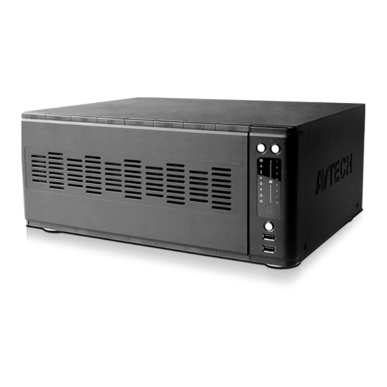
HARDWARE OVERVIEW 1. HARDWARE OVERVIEW 1.1 Front Panel Note: The functions on the front panel may vary, depending on the mode you have. 1) Select & Unlock These two buttons are used to unmount a hard disk. Press Select and check the HDD indicator (red & always on) to ensure the hard disk you want to unmount is chosen. -
Page 7: Rear Panel
HARDWARE OVERVIEW 1.2 Rear Panel Note: The functions on the rear panel may vary, depending on the mode you have. 1) HDMI1 This port is used to connect the monitor which supports HDMI interface for main monitor output 2) HDMI2 This port is used to connect a secondary monitor which supports HDMI interface for secondary monitor output. -
Page 8: Connection
CONNECTION 2. CONNECTION 2.1 Hard Disk Installation Note: It’s necessary to install a hard disk first before firmware upgrade to ensure the upgrade process works properly. Type 1 Step1: Remove the top cover, and find the hard disk connector and bracket in the device. CR2032 Hard Disk Connector... - Page 9 CONNECTION Additional Brackets for Two More Hard Disks Step1: For the 16CH model which supports five hard disks, find two pairs of HDD trays, SATA cables and power cables in the sales package. Step2: Find HDD brackets, power board connectors (white) and Sata board connectors (black) on the main board. To install a hard disk, three brackets, one power board connector (while) and one Sata board connector (black) are needed.
- Page 10 CONNECTION Type 2 Step1: Find the HDD tray and its accessories in the sales package, and place the rubber to the HDD tray as shown below. Step2: Get a compatible hard disk. With the PCB side facing down and the hard disk‘s connector facing the outside. Then, place the hard disk in the HDD tray and insert the latches.
- Page 11 CONNECTION Type 3 Step1: Remove the top cover, and find where to install a hard disk on the recorder. Step2: Get a compatible hard disk. With the PCB side facing down, find the screw holes on the recorder base, and place the hard disk in the recorder.
- Page 12 CONNECTION Add eSATA interface with optional SATA-to-eSATA cable Step1: Check the specifications of your recorder and see if it supports this feature. If yes, find the reserved hole on the rear panel of your recorder as illustrated below. Step2: Remove the top cover of the recorder to reveal its main board. Remove the thin piece of metal that block the reserved hole.
-
Page 13: Connection
CONNECTION 2.2 Connection Connect a monitor, IP cameras, adapters, a mouse, and other devices necessary to this recorder as illustrated below. Type 1 Type 2 Then, power on the whole system and wait till the system initialization is done. -
Page 14: Camera Ip Configurations By Lan
IPCAM 10.2.1.33 255.255.255.0 10.2.1.10 8.8.8.8 00:0E:53:31:06:E5 AVTECH REFRESH The device will automatically configure the IP address of a camera connected by LAN if: The connected IP camera is our brand’s IP camera. Reset the IP camera to default value (the default IP configuration method of the camera is “DHCP”). - Page 15 IPCAM 10.1.1.14 255.255.255.0 10.1.1.10 8.8.8.8 00:0E:53:31:06:E5 AVTECH REFRESH device d) The will then detect the IP camera and display images soon. Note: To configure this recorder to access other IP camera connected remotely for live viewing or video backup, you need to connect this recorder to Internet first.
-
Page 16: For Initial Use
FOR INITIAL USE 3. FOR INITIAL USE For the first time to power on this device, you might be prompted to: Go through the setup wizard Clear hard disk Change default user name and password 3.1 Setup Wizard The setup wizard is prompted to guide you finishing the most common settings you might need to do. - Page 17 FOR INITIAL USE SETUP WIZARD DATE 2015/MAR/05 TIME 14:33:46 FORMAT Y/M/D GMT+08:00 SKIP PREV NEXT Set the date and time. If you don’t want to set the date and time now, just skip to the next step. However, it’s necessary to keep the date and time right to ensure the accuracy of the recorded data.
-
Page 18: Mount Hard Disk
FOR INITIAL USE SETUP WIZARD DDNS SYSTEM NAME Eagleeyes HOST NAME MAC000E533A3D E-MAIL CURRENT HOST ADDRESS MAC000E533A3D4A.ddns.eagleeyes.tw SKIP PREV NEXT Enable DDNS if needed. Note: To enable the DDNS later, please go to MENU NETWORK DDNS. 3.2 Mount Hard Disk When this device is powered on, you’ll see the hard disk indicators are flashing in red, indicating the hard disk are not detected by this recorder. - Page 19 FOR INITIAL USE To change later, go to MENU ACCOUNT USER LIST, and choose to change the default user name and password of SUPERVISOR. USER LIST USER LIST GROUP EDIT USER NAME GROUP admin SUPERVISOR...
-
Page 20: User Interface
USER INTERFACE 4. USER INTERFACE 4.1 Local Access Connect your USB mouse to one of the USB ports on the front panel, and move your mouse to enter the password with the password keypad. The default user name and password are both admin. When you log into the system, the display is in the full screen mode. -
Page 21: Status & Operation
USER INTERFACE 4.3 Status & Operation 4.3.1 Device Status Note: The functions shown may vary based on the model or the access user level you use. Key lock Key unlock Channel lock Channel unlock USB flash drive / device connected No USB device connected Timer record on Timer record off... -
Page 22: Main Menu
FREQUENTLY-USED FUNCTIONS 4.3.3 Main Menu Click MENU on the bottom left corner to show the main menu list and its sub items: CAMERA CONNECTION IP SEARCH DEVICE IMAGE BRIGHTNESS CONTRAST SATURATION DETECTION ALARM OUT (For selected models only) RECORD LIVE STREAM RECORD STREAM SUBSTREAM SCENARIO... - Page 23 FREQUENTLY-USED FUNCTIONS DISPLAY CHANNEL TITLE EVENT STATUS AUTO KEY LOCK(S) HDD DISPLAY MODE DISPLAY OUTPUT LANGUAGE HDMI2 DISPLAY (For selected models only) SPOT MONITOR (For selected models only) COMPOSITE OUTPUT (For selected models only) VGA OUTPUT (For selected models only) CALL SCREEN DURATION QUAD SCREEN DURATION NVR MODE...
-
Page 24: Playback Panel
FREQUENTLY-USED FUNCTIONS 4.3.4 Playback Panel Click to go to the playback panel. Step1: In CHANNEL, choose the channel(s) you want to search. Step2: In DATE, the date(s) which includes video footage of the selected channel(s) will be marked in blue. Choose the date you want. -
Page 25: Frequently-Used Functions
255.255.255.0 10.2.1.10 8.8.8.8 00:0E:53:31:06:E5 AVTECH REFRESH Make sure the IP address of the connected camera is under the network segment of 10.1.1.xx (xx ranges from 11 ~ 253). If not, select and change the network type from STATIC to DHCP. Then, Click... -
Page 26: User Account Creation
FREQUENTLY-USED FUNCTIONS 5.2 User Account Creation To create different user account for different access privilege, go to MENU ACCOUNT USER LIST, and choose to create a new account. USER LIST USER LIST GROUP EDIT USER NAME GROUP admin SUPERVISOR Four user levels are pre-defined in the system for you to quickly choose: SUPERVISOR, POWER USER, USER &... -
Page 27: Ptz Control
FREQUENTLY-USED FUNCTIONS 5.3 PTZ Control Enter Click to confirm your selection / enter the menu. / ⊳ / Up / Down / Left / Right Click the arrow keys ( ) to more the camera lens up / down / left /right. Camera Control This two buttons are designed for the PTZ camera which uses Pelco-D to control. -
Page 28: Video Backup
FREQUENTLY-USED FUNCTIONS Preset Point These ten buttons are used for preset point 1 ~ 10. To set or go to other preset point (such as 15), please enter the numbering manually 01 ~ 10 Preset point 01 ~ 10 in the input box next to , and choose to set the preset point, or to go... -
Page 29: System Logout
FREQUENTLY-USED FUNCTIONS Step3: The video footage can only be saved to a USB device. Specify where to save in the USB device in STORAGE. Step4: Choose BACKUP to start. The backup video will be in the AVI format. Note: When the video compression format is H.265, please use the video player which supports H.265 to play the video footage. -
Page 30: Main Menu
MAIN MENU 6. MAIN MENU 6.1 CAMERA 6.1.1 CONNECTION To know how to add our brand’s IP cameras automatically, please refer to “2.3 Camera IP Configurations by LAN” at 9. To manually add a camera connected locally or remotely, click to enter the setup page. -
Page 31: Device
MAIN MENU 6.1.2 DEVICE DEVICE CHANNEL TITLE ENABLE CACHE TIME (MSEC) PORT CAMERA ALARM OUT OSD TITLE OSD LOGO FORWARD TYPE AUTO UP LEFT UP LEFT AUTO UP LEFT UP LEFT AUTO UP LEFT UP LEFT AUTO UP LEFT UP LEFT APPLY 1) CHANNEL TITLE Click to revise the channel title (up to 63 characters). -
Page 32: Image
MAIN MENU 6) ALARM OUT (Depending on the camera you connected) This function is used to set how long the device should work in seconds when the is clicked on the camera channel. Note: An alarm-out device (such as a buzzer) should be connected to an IP camera first for this function to take effects. - Page 33 MAIN MENU 6) ADVANCED CONFIG The advanced settings are available only when the connected camera supports. Analytics Video The options within this function should work with CMS PRO to take effects. For details, please check with your installer or distributor. PRIVACY MASK SCENE CHANGE DEFOCUS...
- Page 34 MAIN MENU ROI (Region of Interest) ROI is used to reinforce the image quality of the selected area(s). Users could specify two areas in the camera view. REGION OF INTEREST REGION ENABLE QUALITY EDIT Select REGION 1 or REGION 2, and choose EDIT to change the setting. REGION OF INTEREST –...
-
Page 35: Alarm Out
MAIN MENU 6.1.5 ALARM OUT Note: An alarm-out device (such as a buzzer) should be connected to an IP camera first for this function to take effects. To configure the alarm-out device connected to the recorder itself, please refer to “6.11.3 ALARM OUT” at page 54. This function is used when the external alarm-out device is connected to an IP camera. - Page 36 MAIN MENU LIVE VIDEO SOURCE CONFIG LIVE RECORD STREAM SUBSTREAM CHANNEL D.O.R PROFILE TYPE IMAGE SIZE QUALITY I.P.S. BITRATE (kbps) BITRATE CONTROL G.O.V. PROFILE-3 H265 720 X 480 2048 PROFILE-3 H264 1280 x 1024 2048 PROFILE-3 H264 1280 x 1024 2048...
-
Page 37: Scenario
MAIN MENU 6.3 SCENARIO This function allows you to customize a series of actions which will be run automatically after the specified event occurs. Several scenario rules are pre-defined for you to quickly choose and apply. If none of these rules are suitable for you, you can choose to create your own rule from several scenario templates. - Page 38 MAIN MENU 5) PUSH VIDEO TRIGGERED BY EXTERNAL ALARM (For selected models only) When motion & alarm events occur simultaneously, you’ll receive Push Video on your mobile device. Scenario template used: ALL OF (EVENTS) TO DO (ACTION) AND THEN (ACTION). Note: The alarms here refer to the alarm devices connected to the IP cameras or the NVR.
-
Page 39: Scenario Customization
MAIN MENU HDMI2 DISPLAY. For details, please refer to “6.10 DISPLAY” at page 50. DISPLAY 6.3.2 Scenario Customization Note: The functions available depend on the recorder you have. Click and choose a template where you can press the button of EVENT, RECORD, TIME or ACTION to customize all your events and further actions: 1. - Page 40 MAIN MENU...
- Page 41 MAIN MENU RECORD Option Description START RECORDING EVENT GROUP Choose the record profile group you want defined CHANNEL in MENU RECORD RECORD STREAM when event recording is on. TIME Option Description EVERYDAY Choose the pre-defined time range within which you want to activate the scenario rule. HOLIDAY WEEKDAY Click...
- Page 42 MAIN MENU each setting page. Option Description CAMERA PRESET Choose the channel with a speed dome camera connected, and choose a preset point you want the camera to move to. To know how to set a preset point, please refer to “5.3 PTZ Control”...
-
Page 43: Ivs
MAIN MENU 6.4 IVS This function is available only when the connected IP camera supports this function. IVS MODE DISPLAY LINE SCENE CHANGE SCENE CHANGE LEVEL SENSITIVITY FLOW COUNTING MIDDLE ONEWAY MIDDLE 1) IVS MODE Select one of the following three modes depending on your environment: MODE DESCRIPTION FLOW COUNTING... - Page 44 MAIN MENU IVS APPLICATION Step1: Click to enter the setting page and draw a detection line with your mouse, and decide the detection direction by selecting REVERSE. Step2: Click APPLY to finish the IVS setting and return to the live view. When anyone walks across the detection line, the system will determine his movement is in or out, and add one count to the corresponding channel on the flow counting panel.
- Page 45 MAIN MENU Step1: Click to enter the setting page and draw a detection line with your mouse, and decide the detection direction by selecting REVERSE. Step2: Click APPLY to finish the IVS setting and return to the live view. When anyone walks across the detection line, the system will determine his movement is in or out, and: An event happens for anyone walking across the detection line, and “...
-
Page 46: Export
MAIN MENU 6.5 EXPORT 6.5.1 BACKUP Note: Before using your USB flash drive for video backup, please format it to "FAT32” first with your PC or laptop. For the list of compatible USB flash drives, please refer to “APPENDIX 3 COMPATIBLE USB FLASH DRIVE LIS at page 75. -
Page 47: Schedule
MAIN MENU STORAGE. Step4: Choose BACKUP to start. The backup video will be in the AVI format. Note: When the video compression format is H.265, please use the video player which supports H.265 to play the video footage. 6.5.2 SCHEDULE This function is used to schedule video backup regularly, uploading security footages to a FTP site (remotely) or saving to an USB device connected to this device (locally). -
Page 48: Regular Report
MAIN MENU 6.5.3 REGULAR REPORT This function is used to send event reports to the specified E-mail address. Users could configure up to 5 profiles to receive different reports about specific channels at different time. Note: This function is available only when a hard disk is installed, and the recorder is connected to Internet. -
Page 49: Storage
MAIN MENU 6.6 STORAGE In this menu, you can check the status of each connected hard disk and configure some precaution actions to protect each hard disk and the video data saved in it such as reminding of hard disk erasing or avoiding the hard disks being over-heated. -
Page 50: Account
MAIN MENU Mount / Unmount HDD HDD hot-swapping is supported for this device. There’s no need to power off the device first to install or remove a hard disk. When a hard disk is installed, you’ll need to click to manually mount the hard disk for it to work properly. When you need to remove a hard disk, click to unmount the hard disk and you’ll be able to remove it. -
Page 51: Group
MAIN MENU 6.7.2 GROUP This menu is used to create a new group with customized user access rights for different functions if needed, and you can create a user account and assign it to your customized group. Note: The default user groups are SUPERVISOR, POWER USER, USER and GUEST, and they’re not allowed to be removed. -
Page 52: Network
MAIN MENU 6.8 NETWORK There are two RJ45 ports on the rear panel: WAN and LAN. WAN is used to connect this recorder to Internet for remote access from anywhere as long as Internet access is available. LAN is used to connect to IP cameras locally. ... -
Page 53: Ftp
MAIN MENU 6.8.2 FTP Configure up to 7 FTP sites here to upload event notifications or reports. FTP 1 FTP 2 FTP 3 FTP 4 FTP 5 FTP 6 FTP 7 NAME Profile1 SERVER 211.75.33.2144 PORT USER NAME office PASSWORD APPLY 6.8.3 MULTICASTING In this menu, users could configure the multicast address and port used for each channel for data streaming. -
Page 54: Eazy
MAIN MENU 6.8.4 EaZy This function is used to connect this recorder to Internet by using EaZy Networking. For details, please refer to “APPENDIX 7 EAZY NETWORKIN” at page 79. EaZy ENABLE EAZY NETWORKING MAC: 000e53eca7b4 UUID: E736DCBF-D4BB-4CA8-86FD-62658E2ECEC1 PORT: 80 EAZY NETWORKING OFFLINE 6.9 TIME TIME SETUP... -
Page 55: Display
MAIN MENU 6.10 DISPLAY DISPLAY CHANNEL TITLE EVENT STATUS AUTO KEY LOCK(S) HDD DISPLAY MODE RE,MAINING SIZE DISPLAY OUTPUT AUTO LANGUAGE ENGLISH HDMI2 DISPLAY SETUP (For selected models only) SPOT MONITOR SETUP (For selected models only) COMPOSITE OUTPUT SETUP (For selected models only) VGA OTUPUT MAIN MONITOR (For selected models only) - Page 56 MAIN MENU EVENT MONITOR is used when any alarm event occurs. When this option is selected, go to LAYOUT to select how many channels you want to see, and PRE-ALARM (SEC) and POST-ALARM (SEC) to set how many seconds you’d like to see before (0 ~ 5) and after (3 ~ 10) the event starts.
- Page 57 MAIN MENU EVENT MONITOR is used when any alarm event occurs. When this option is selected, go to LAYOUT to select how many channels you want to see, and PRE-ALARM (SEC) and POST-ALARM (SEC) to set how many seconds you’d like to see before (0 ~ 5) and after (3 ~ 10) the event starts.
- Page 58 MAIN MENU EVENT MONITOR is used when any alarm event occurs. When this option is selected, go to LAYOUT to select how many channels you want to see, and PRE-ALARM (SEC) and POST-ALARM (SEC) to set how many seconds you’d like to see before (0 ~ 5) and after (3 ~ 10) the event starts.
-
Page 59: Peripheral
MAIN MENU 6.11 PERIPHERAL 6.11.1 LOCAL LOCAL MOUSE SENSITIVITY REMOTE CONTROL ID 1) MOUSE SENSITIVITY Select the mouse sensitivity. The higher the value, the more sensitive the mouse. 2) REMOTE CONTROL ID This function is available when users need to control two or more recorders with one IR remote controller. The ID set here is used to identify the recorder the remote controller is going to control. - Page 60 MAIN MENU...
-
Page 61: Local Alarm In
MAIN MENU 6.11.4 LOCAL ALARM IN Note: This function is available for the models which support alarm-in connection to the recorder itself. Please check the specifications of your recorder to know if your recorder supports this function. This function is used when the external alarm-in device is connected directly to the recorder. You can configure how the alarm device should work by choosing N.O. -
Page 62: Upgrade
MAIN MENU 6) RESET ALL GUARD CONNECTION (For selected models only) When there’re more than 2 users who have the authority to enable Push Video on their mobile devices and configure its related settings, it might be confusing to know whose command is working. In this case, use this function could force the camera to discard all Push Video setup and reconfigure it. -
Page 63: Alert
MAIN MENU Step3: Repeat Step2 as many as needed until all cameras which need firmware upgrade are selected. If one firmware file applies to several IP cameras, select COPY TO to apply the same file to the applicable cameras. Step4: Choose UPGRADE to start upgrading all selected cameras, or choose to upgrade the camera one by one. -
Page 64: Online
MAIN MENU 6.12.5 ONLINE ONLINE ANONYMOUS VIEWER LOGIN DROP ALL CONNECTION SUBMIT LOGIN FAILURE TIMES LOCK TIME FOR LOGIN FAILURES 10 MINS 1) ANONYMOUS VIEWER LOGIN Switch to ON to allow anonymous login, meaning there’s no need to enter user name and password for remote access. -
Page 65: Remote Operation
REMOTE OPERATION 6. REMOTE OPERATION You can also control this recorder remotely via the web browser and iOS / Android devices. 6.2 Web Browser You can view the images or operate your recorder with a web browser, for example, Windows Edge, Microsoft Internet Explorer, Google Chrome, Mozilla Firefox &... -
Page 66: Mobile Devices
REMOTE OPERATION 6.3 Mobile Devices Note: For more details about mobile surveillance via your mobile device, please visit http://info.eagleeyes.tw/iphone/index.html. EagleEyes is a mobile phone program used with our surveillance system for remote surveillance. It’s compatible with iOS and Android mobile devices, and it’s free (Except EagleEyes Plus for iOS OS, and EagleEyes Plus+ for Android OS). - Page 67 REMOTE OPERATION Step3: In the setting page, enter all the information needed to access this device in the REQUIRED column, and click Get Type to examine if the information you entered is correct. The device type will be detected properly. Step4: (Optional) Configure the settings in the OPTIONAL column as needed.
-
Page 68: Appendix 1 Product Specifications
APPENDIX 1 PRODUCT SPECIFICATIONS APPENDIX 1 PRODUCT SPECIFICATIONS 16CH Models (without 8-bay & PoE) Model 1 Hardware Video Input One LAN port (up to 16 IP cameras) Video Output HDMI x 2 / VGA x 1 HDMI-1: Up to 3840 x 2160 (4K2K) Video Output Resolution HDMI-2 &... - Page 69 APPENDIX 1 PRODUCT SPECIFICATIONS...
- Page 70 APPENDIX 1 PRODUCT SPECIFICATIONS Model 1 Software Spot Monitor Setup Call Monitor / Event Monitor / Live Monitor (HDMI-2 only) Alarm Scenario Setup Alarm Pop-up & Preview Free DDNS Service General Power Source (±10%) DC19V / 4.7A Operating Temperature 10℃ ~ 40℃ (50℉~104℉) Operating Humidity 10% ~ 85% Dimensions (mm)***...
- Page 71 APPENDIX 1 PRODUCT SPECIFICATIONS 36CH & 16CH Models (with 8-bay) Model 2 Model 3 Model 4 Model 5 Hardware One LAN port (up Video Input One LAN port (up to 36 IP cameras) to 16 IP cameras) HDMI x 1 / HDMI x 2 / Video Output HDMI x 2 / VGA x 1 / Composite x 1...
- Page 72 APPENDIX 1 PRODUCT SPECIFICATIONS Model 2 Model 3 Model 4 Model 5 Software Push Video / Push Push Video / Push Event Notification Status / Video Mail / Push Status / Video Mail / Message Mail Status / Video Mail / Message Mail Message Mail Security...
- Page 73 APPENDIX 1 PRODUCT SPECIFICATIONS 16CH & 9CH Models with PoE Model 6 Model 7 Model 8 Model 9 Hardware Video Input 8 LAN ports with PoE Video Output HDMI YES (4K2K) YES (1080P / Spot Monitor Supported) COMPOSITE YES (Spot Monitor Supported) 16CH Mode: 1080P Video Output Resolution 4K2K...
- Page 74 APPENDIX 1 PRODUCT SPECIFICATIONS Model 6 Model 7 Model 8 Model 9 Software Push Video / Push Push Status / Push Video / Push Push Status / Event Notification Status / Video Mail Video Mail / Status / Video Mail Video Mail / / Message Mail Message Mail...
- Page 75 APPENDIX 1 PRODUCT SPECIFICATIONS 4CH Models with PoE Model 10 Model 11 Hardware Video Input 4 LAN ports with PoE Video Output HDMI YES (4K2K) YES (1080P / Spot Monitor Supported) COMPOSITE Video Output Resolution 4K2K Audio Output Audio Input Alarm I/O RS485 Either one 14TB SATA HDD installed in the recorder,...
- Page 76 APPENDIX 1 PRODUCT SPECIFICATIONS Model 10 Model 11 Software IVS*** YES (4CH) Spot Monitor Setup Call Monitor / Event Monitor / Live Monitor (VGA) Alarm Scenario Setup Alarm Pop-up & Preview Free DDNS Service General Power Source (±10%) DC48V / 1.25A PoE**** IEEE802.3af Operating Temperature...
-
Page 77: Appendix 2 Push Video Configuration
APPENDIX 2 PUSH VIDEO CONFIGURATION APPENDIX 2 PUSH VIDEO CONFIGURATION Note: This function is for selected models only. Please check the product specifications or check with your installer to know more details. A2.1 Alarm Sensor Connection Connect the alarm sensor, such as magnetic contacts, to the alarm-in port on the rear panel. Alarm-in 1 corresponds to video channel 1, alarm-in 2 corresponds to video channel 2, and so on. -
Page 78: A2.2 Configuration
APPENDIX 2 PUSH VIDEO CONFIGURATION A2.2 Configuration Before configuring Push Video, make sure: 1. The system is set up as described in “2. CONNECTION” at page 3. 2. This recorder is connected to Internet. 3. You’ve installed the app, EagleEyes, on your iOS or Android mobile devices. For details, please refer to “6.3 Mobile Devices”... -
Page 79: A2.3.2 From Android Mobile Device
APPENDIX 2 PUSH VIDEO CONFIGURATION Step2: Open EagleEyes, and switch Guard to ON. You’ll receive the message indicating that Push Video is Step3: Return to the main page or standby page. You’ll receive event notifications when there’s an alarm event. Follow the on-screen instruction to immediately play the recorded clip. -
Page 80: Appendix 3 Compatible Usb Flash Drive List
APPENDIX 3 COMPATIBLE USB FLASH DRIVE LIST APPENDIX 3 COMPATIBLE USB FLASH DRIVE LIST Please upgrade the firmware of the recorder to the latest version to ensure the accuracy of the following table. If the USB flash drive is not supported by the recorder, you will see on the screen. -
Page 81: Appendix 4 Compatible Hard Disk List
APPENDIX 4 COMPATIBLE HARD DISK LIST APPENDIX 4 COMPATIBLE HARD DISK LIST Please upgrade the firmware of the device to the latest version to ensure the accuracy of the following table. Note: It’s necessary to install a hard disk first before firmware upgrade to ensure the upgrade process works properly. -
Page 82: Appendix 5 Battery Replacement
APPENDIX 5 BATTERY REPLACEMENT APPENDIX 5 BATTERY REPLACEMENT The time reset after power failure, for example, caused by a power outage, will cause the disorder of the recorded data, and users may have problems in searching the event clip they want. To keep the device time from resetting, a non-chargeable lithium battery, CR2032, is installed in the device. -
Page 83: Appendix 6 Disk Array Compatible List
APPENDIX 6 DISK ARRAY COMPATIBLE LIST APPENDIX 6 DISK ARRAY COMPATIBLE LIST Here's the compatible list for disk arrays. Note: For the compatible hard disks used for those disk arrays listed below, please check their respective user manuals or official websites. Brand Model Number Proware... -
Page 84: Appendix 7 Eazy Networking
APPENDIX 7 EAZY NETWORKING APPENDIX 7 EAZY NETWORKING EaZy Networking is a free P2P cloud service to connect AVTECH devices to the Internet automatically by plug-and-play, enabling you to check the live view via your mobile device or laptop at anytime. - Page 85 APPENDIX 7 EAZY NETWORKING A8.1.2 EagleEyes Setup Two options can be chosen for EaZy Networking: EaZy and QR Code. EaZy is used for both recorders and IP cameras while QR Code is used only for recorders. When a device is configured to the internet via EaZy, the person who configures the device has the administrator permission of this device and also has the power to assign who can access the device remotely, by the web browser of Internet Explorer or the mobile app of EagleEyes.
- Page 86 APPENDIX 7 EAZY NETWORKING Step3: Go back to the address book and click + to add a new device. Select EaZy, and choose the recorder icon to continue. Step4: Click in the section of MAC address to open the QR code scan page, and scan the QR code on the recorder screen mentioned in Step2.
- Page 87 APPENDIX 7 EAZY NETWORKING A8.1.3 Checking Remaining Data Allowance Step1: Log into the cloud service. Step2: Select Details to go to account information, and select Available Data Allowance. A8.1.4 Sharing Cloud Device Access with Other Account(s) Note: One cloud device could be shared up to 30 cloud accounts, but the access to the device might be failed because it is still restricted to the maximum online user setup of the device.
- Page 88 APPENDIX 7 EAZY NETWORKING Step3: Choose the device you want to share with. Step4: Enter the cloud account or the E-mail registered by the account, and select Add. Step4: Check again the account with which you want to share your cloud device, and select Next to confirm and continue.
-
Page 89: A8.2 Via Internet Explorer On Pc / Laptop
APPENDIX 7 EAZY NETWORKING Step6: Check again the configurations you made for the account to which you want to share your cloud device, and select Share! to confirm. Step7: (Optional) Configure the data allowance shared to other accounts to use. Step8: Return to the address book of EagleEyes. - Page 90 APPENDIX 7 EAZY NETWORKING Step2: In the same menu, select EaZy. Enable EaZy Networking, and leave this page open. You’ll need to scan the QR code later. EaZy ENABLE EAZY NETWORKING DDNS E-MAIL MULTICASTING EaZy Step3: Open Internet Explorer on a PC / laptop, and enter https://ez.eagleeyes.tw. In the login page, register an account for “Cloud Service”.
- Page 91 APPENDIX 7 EAZY NETWORKING Click Apply to continue. Step7: When your device is found, you’ll be directed to the next page to change the device title if you want. Note: The device name changed here will be fixed and can’t be changed later. Click Apply to continue.
- Page 92 APPENDIX 7 EAZY NETWORKING A8.2.2 Checking Remaining Data Allowance Step1: Log into the cloud service. Step2: Select “Account Information” on the top right corner to go to account information, and select Available Data Allowance. A8.2.3 Sharing Cloud Device Access to Other Account(s) Note: One cloud device could be shared up to 30 cloud accounts, but the access to the device might be failed because it is still restricted to the maximum online user setup of the device.
- Page 93 APPENDIX 7 EAZY NETWORKING Step4: Check again the account to which you want to share your cloud device. To add more accounts, select Add; to remove the existing account, select Delete; to continue buddy setup, select Next. Step5: Specify the access permission of the specified account, which account’s data allowance should be consumed after access successfully, and how long the account is allowed to stay after access successfully.
-
Page 94: A8.3 Icons
The cloud icon will be grayed out if the EaZy server can’t be connected. You’ve shared the access right of the device with other cloud account via Buddy (AVTECH Cloud Service). Depending on the device color The icon will be grayed out if you disable the device share.
Need help?
Do you have a question about the H.265 NVR Series and is the answer not in the manual?
Questions and answers