
Related Manuals for ChallengerOptics CO-OPM-PON


Summary of Contents for ChallengerOptics CO-OPM-PON
-
Page 1: Table Of Contents
CO-OPM-PON / Interactive Operating Manual Best viewed with Adobe Acrobat Reader 1.0 Introduction 2.6 Menu Options and Settings 1.1 Description 2.6.1 Threshold Selection & Setup 8 1.2 Special Features Pass / Fail Threshold Selection 8 1.3 Specifications Threshold Value Setup 1.3 Accessories... -
Page 2: Introduction
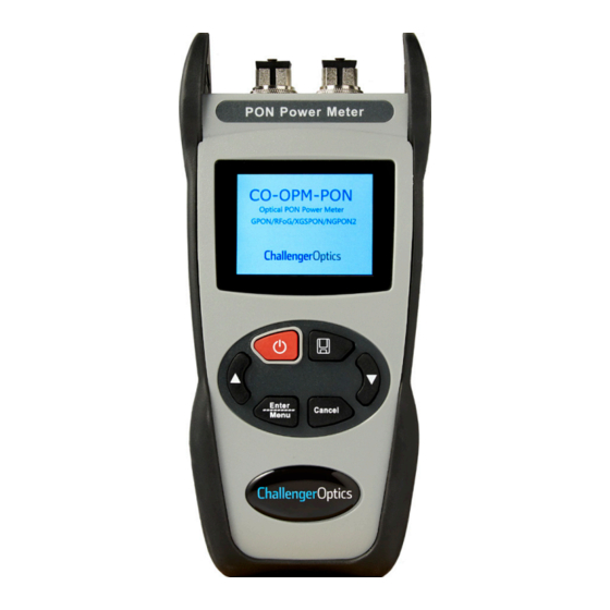
Contents CO-OPM-PON 1 Introduction 1.1 Description The next generation CO-OPM-PON power Meter is used to measure E-PON, G-PON, XGS-PON, and 10G-EPON. Also in RFoG. It also combine the function of pass/fail for network trouble shooting. 1.2 Special Features - Simultaneously measures RFoG, XGS-PON, G-PON. -
Page 3: Accessories
1 ea 1.5 Powering 3 AA1.5V battery 1.6 Meter Care Do not subject the CO-OPM-PON to strong impact. The CO-OPM-PON is not water resistant or waterproof Do not disassemble. Always properly clean the fiber interfaces before taking a measurement. Always replace the Dust Cap for dust protection. -
Page 4: Getting Started
Contents CO-OPM-PON 2 Getting Started 2.1 Explanation of Operating Keys Function Power ON/OFF. Hold for 2 sec to power ON / OFF. AUTO / OFF Save Measurement Reading Enter Cancel Menu Enter Cancel Previous request; move to previous menu option... -
Page 5: Key Functions
Contents CO-OPM-PON 2.2 Key Functions: Press for 3 sec. to turn on the device. Short press to enable/disable the auto-off function. Icon on left top of the screen, Enter Cancel Menu displays the status of auto-off capability Press/Hold for 3 sec. to power off. -
Page 6: Measurement Mode
Contents CO-OPM-PON 2.3 Measurement Mode There are 3 measurement modes: All Channels / (1270 / 1310 / 1490 / 1550 / 1577 / 1610nm) RFoG + XGS-PON (1270 / 1577nm, 1550 / 1610) Standard PON (1310 / 1490 / 1550) ▼... -
Page 7: Data Storage
Contents CO-OPM-PON 2.4 Data Storage To save a measurement, press Current data group for save (up to 500) The current data group number will be displayed (up to 500). Enter Cancel Menu Press to confirm the save, Enter... -
Page 8: Menu Options And Settings
Contents CO-OPM-PON 2.6 Menu Option and Settings Press to enter into Menu function. Enter Cancel Menu There are 3 Options on the menu: - Threshold - Date & Time - Record 2.6.1 Threshold Selection and Setup Pass/Fail Threshold Selection... -
Page 9: Threshold Value Setup
Contents CO-OPM-PON There are 10 groups of Pass/Fail Threshold settings. Each group has a minimum Threshold for each Wavelength: 1310/1490/1550/1270/1577/1610. ▼ Use the to navigate through the 10 Threshold groups / Disable. Press Enter to choose a Threshold group. - Page 10 Contents CO-OPM-PON p 10 After choosing the threshold group, press Enter Cancel Menu “ ” will move to the 1st wavelength. The “ ” will indicate the wavelength being set up. ▲▼ Use the to adjust the threshold value, in 0.5dB steps.
-
Page 11: Time / Date Setting
Contents CO-OPM-PON p 11 2.6.2 Time & Date Setting Press to enter into Main Menu, using Enter Cancel Menu ▲▼ , choose Date & Time. Press button to enter into Date & Enter Cancel Menu Time setting. The Blue marks the field being adjusted. -
Page 12: Record
Contents CO-OPM-PON p 12 2.6.3 Record Enter into Main Menu by pressing Enter Cancel Menu ▲▼ Press to Choose the Third Option: Record. In the Record Option, there are 3 options: - Check Record - Delete View - Delete All. -
Page 13: Delete Measurement Record
Contents CO-OPM-PON p 13 Delete Measurement Record Delete/Record? Y/N Within the “Record” option, choose “Delete View” to delete a specific measurement record. Use ▲▼ to select measurement record for deletion. ENTER to delete. You will be prompted again by “?”... -
Page 14: Software
14 3 Software The CO-OPM-PON meter has a USB port with USB cable, as well as the related driver software. USB cable is used for data upload and self calibration function. For the details of the software functionality, please refer to the software instruction on the USB stick provided.
Need help?
Do you have a question about the CO-OPM-PON and is the answer not in the manual?
Questions and answers