Advertisement
Quick Links
PROPER USE GUIDELINES
Cumulative Trauma Disorders can result from the prolonged use of manually powered hand tools. Hand tools are intended for occasional use and low volume
applications. A wide selection of powered application equipment for extended- - use, production operations is available.
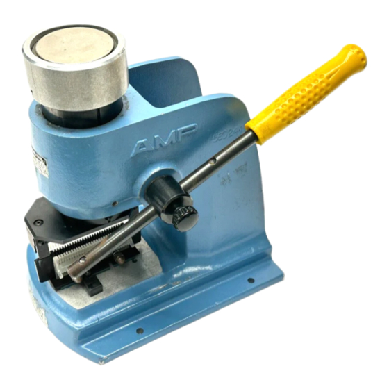
Plug Button
Mounting Holes
(4 Places)
1. INTRODUCTION
Manual Arbor Frame Assembly 58024--1, shown in
Figure 1, provides the necessary force to drive
various tooling assemblies (upper and lower tooling)
to be used for a specific purpose.
Dimensions in this instruction sheet are in
NOTE
millimeters [with inches in brackets]. Figures are
i
not drawn to scale.
Reasons for reissue of this instruction sheet are
provided in Section 7, REVISION SUMMARY.
2. DESCRIPTION
The arbor frame assembly features a bench--
mountable frame, base plate, handle, handle
adjusting knob, adjustment ring, and ram. The handle
is adjustable for storage.
3. SETUP AND OPERATION
1. Grasp the handle, and loosen the handle
adjustment knob sufficiently for the handle to slide.
FULLY extend the handle. Tighten the knob,
E2011 Tyco Electronics Corporation, a TE Connectivity Ltd. Company
All Rights Reserved
TE logo is a trademark.
*Trademark. Other product names, logos, or company names might be trademarks of their respective owners.
Manual Arbor Frame Assembly
58024- 1
Frame
TOOLING ASSISTANCE CENTER 1--800--722--1111
PRODUCT INFORMATION 1--800--522--6752
Setscrew
Adjustment
Ring
Ram (Retracted)
Base Plate
Figure 1
making sure that the screw enters the last hole in
the handle.
2. Secure the arbor frame assembly to a
workbench to ensure stability during operation.
Refer to Figure 2 for mounting hole dimensions.
Mounting Hole Dimensions
127 [5]
Front of Arbor Frame Assembly
This controlled document is subject to change.
For latest revision and Regional Customer Service,
visit our website at www.te.com
Instruction Sheet
408- - 6923
11 Mar 11 Rev D
Handle
Handle Adjusting Knob
50.8 mm
[2 in.] (Ref)
172.2 [6.78]
7.14 [.281]
Dia
164.6 [6.48]
Figure 2
1 of 3
LOC B
Advertisement

Related Manuals for TE Connectivity 58024-1


Summary of Contents for TE Connectivity 58024-1
- Page 1 Figure 2 FULLY extend the handle. Tighten the knob, 1 of 3 E2011 Tyco Electronics Corporation, a TE Connectivity Ltd. Company TOOLING ASSISTANCE CENTER 1--800--722--1111 This controlled document is subject to change. All Rights Reserved...
- Page 2 408- 6923 3. Secure the appropriate upper tooling to the ram If the adjustment ring is NOT held in place when CAUTION according to the instructions packaged with the the pinion is removed, the ram will drop and the upper tooling. adjustment ring will slam onto the frame.
- Page 3 408- 6923 8. Re--assemble the handle and upper tooling and representative, or call 1--800--526--5142, or send a lower tooling. Ensure proper alignment of tooling facsimile of your purchase order to 717--986--7605, or before operating the arbor frame assembly. write to: 9.
Need help?
Do you have a question about the 58024-1 and is the answer not in the manual?
Questions and answers