Table of Contents
Advertisement
Quick Links
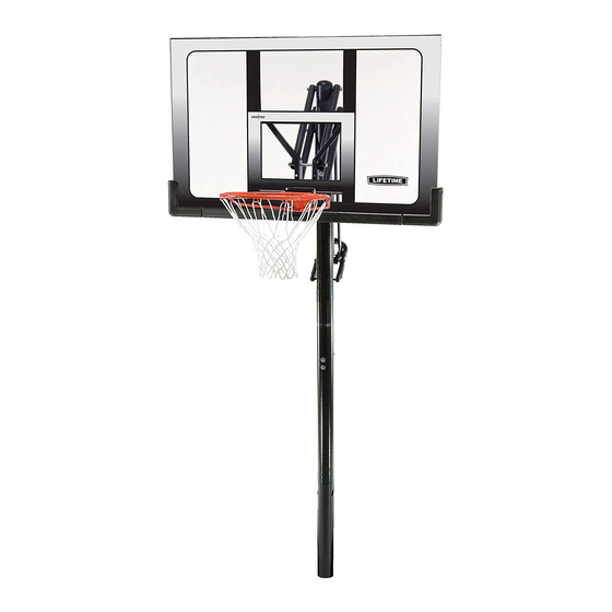
POWER LIFT
BASKETBALL SYSTEM
Lifetime basketball systems are designed to be
strong and durable. We strive to make assembly as
easy as possible without compromising quality. If
you get stuck, we have tools to help:
• Prepare the Area
Before you start, you will need at least six 80-lb.
bags of concrete mix. Before digging, call to locate
any buried utility lines.
• Recruit Friends and Family
Assembly should take 3 people about 3-4
hours to complete.
Save this instruction in the event that the manufacturer
has to be contacted for replacement parts.
TOOLS REQUIRED
3/4" (19 mm)
11/16" (18 mm)
(2)
(1)
(1)
(1)
NEED HELP? TALK TO US!
Call: 1-800-225-3865
7:00 am-5:00 pm (Monday-Friday) MST
and 9:00 am-1:00 pm Saturday MST
®
9/16" (14 mm)
(2)
(2)
(1)
(1)
(1)
30" (762 mm)
(1)
Rebar
Lifetime's assembly experts offer quick responses and great customer service.
Web: www.lifetime.com/instructions
Live Chat: www.lifetime.com/instructions
1/2" (13 mm)
(2)
(1)
Cement
(1)
6-90-lb. bags
(1)
(1)
MODEL# AND PRODUCT ID
Model Number:
90698
TABLE OF CONTENTS
Icon Legend................................2
Notices....................................3
Ground Preparation.....................4
Pole Assembly.............................9
Backboard to Rim Assembly.......14
Backboard to Pole Assembly......20
Handle Assembly.......................29
Final Assembly..........................36
Maintenance Instructions..........43
Registration...........................43
Warning Sticker........................44
Warranty................................47
(you will need both when contacting us)
Product ID:
Advertisement
Table of Contents

Related Manuals for Lifetime POWER LIFT


Summary of Contents for Lifetime POWER LIFT
-
Page 1: Table Of Contents
Maintenance Instructions..43 Registration......43 Warning Sticker......44 30” (762 mm) Warranty........47 Rebar Lifetime’s assembly experts offer quick responses and great customer service. NEED HELP? TALK TO US! MODEL# AND PRODUCT ID (you will need both when contacting us) Call: 1-800-225-3865 Web: www.lifetime.com/instructions... -
Page 2: Icon Legend
CONTACT US • Save this instruction in the event that the manufacturer has to be contacted for replacement parts. Call: 1-800-225-3865 7:00 am–5:00 pm (Monday–Friday) MST and 9:00 am–1:00 pm Saturday MST www.lifetime.com/instructions 1172647 C 2/25/2016... -
Page 3: Notices
WARNINGS & NOTICES WARNINGS & NOTICES / AVERTISSEMENTS ET AVIS / ADVERTENCIAS Y AVISOS SAFETY INSTRUCTIONS FAILURE TO FOLLOW THESE WARNINGS MAY RESULT IN SERIOUS INJURY OR PROPERTY DAMAGE AND WILL VOID WARRANTY. Owner must ensure that all players know and follow these rules for safe operation of the system. To ensure safety, do not attempt to assemble this product without following the instructions carefully. -
Page 4: Ground Preparation
GROUND PREPARATION HARDWARE REQUIRED PARTS REQUIRED Metal Parts ALE (x1) Paper Parts BGW (x1) TOOLS REQUIRED 30” Rebar Level Cement Mix... - Page 5 SECTION 1 (CONTINUED) TOOLS AND HARDWARE REQUIRED • Dig a round hole 24” deep and 21” in diameter. If you live in an area where frost heaves may pose a problem, consult your local building inspector to determine the proper hole depth. The edge of the hole should be fl ush with the edge of the playing surface.
- Page 6 SECTION 1 (CONTINUED) TOOLS AND HARDWARE REQUIRED (9 Bags, 80 lb each) • Make a mark 16 inches from the dimpled end of the Bottom Pole (ALE) (do not scratch the powder coating). Slide the Alignment Frame (BGW) over the Bottom Pole. 16”...
- Page 7 SECTION 1 (CONTINUED) TOOLS AND HARDWARE REQUIRED 30” Rebar • Slide the dimpled end of the Bottom Pole (ALE) into the cement up to the 16-inch mark. Position the pole next to the playing surface. For regulation courts, the Alignment Frame (BGW) should cross the playing surface at the middle of the scored measurements.
- Page 8 SECTION 1 (CONTINUED) TOOLS AND HARDWARE REQUIRED • Mix the remaining 1/2 bag of concrete. Fill the Bottom Pole (ALE) with concrete until it reaches the top of the rebar (about 15” from the top of the pole). Tamp the concrete down in the Bottom Pole with a broom handle to remove air pockets.
-
Page 9: Pole Assembly
POLE ASSEMBLY HARDWARE REQUIRED Hardware Bag CMV (x2) ANE (x2) 5” (Not actual length) ANF (x2) AAA (x2) AAF (x2) PARTS REQUIRED Metal Parts ALF (x1) ALH (x1) ALL (x1) ALM (x1) TOOLS REQUIRED... - Page 10 SECTION 2 (CONTINUED) TOOLS AND HARDWARE REQUIRED 5” AAF (x2) (Not actual length) ANF (x2) ANE (x2) • After allowing the concrete to cure for at least 72 hours, insert the Hex Bolts (ANF) with the Washers (AAF) into the Top Pole (ALH) as shown. Then slide the Spacers (ANE) onto the Hex Bolts. Large holes Small holes...
- Page 11 SECTION 2 (CONTINUED) TOOLS AND HARDWARE REQUIRED 9/16" (x2) AAA (x2) • Place the Pole Bracket (ALL) onto the Hex • Insert the slotted end of the Middle Pole (ALF) into Bolts (ANF), and attach it to the Top Pole the fl...
- Page 12 SECTION 2 (CONTINUED) TOOLS AND HARDWARE REQUIRED • In order to seat the Poles, strike each end of the Pole very hard fi ve to six times on a piece of scrap wood or cardboard. This must be done even if the Poles cover the slot before seating has occurred. •...
- Page 13 SECTION 2 (CONTINUED) TOOLS AND HARDWARE REQUIRED CMV (x1) • After the Poles have been seated, measure up one inch from the bottom center of the Top Pole (ALH) and insert one Self-Drilling Screw (CMV) into the back of the Pole as shown. Then insert the Pole Cap (ALM) into the Top Pole. Save the remaining Screw for use in Section 5.
-
Page 14: Backboard To Rim Assembly
BACKBOARD TO RIM ASSEMBLY HARDWARE REQUIRED Hardware Bag (x2) ADR (x4) AAV (x2) AAQ (x2) ABK (x4) Hardware shown at 50% of Actual Size Hardware shown at 25% of Actual Size APY (x1) APZ (x1) AOW (x1) AJW (x2) ABQ (x1) PARTS REQUIRED Platic Parts (Not shown at actual size) Metal Parts (Not shown at actual size) - Page 15 SECTION 3 (CONTINUED) TOOLS AND HARDWARE REQUIRED 1/2” (13 mm) ABQ (x1) AAQ (x1) (Not to scale) APY (x1) (Not to scale) (x2) • Insert two Carriage Bolts (EAP) through the Rim Pivot Bracket (APY) as shown. • Use the 1/2” socket head from the socket head wrench to press one Push Nut (AAQ) onto one end of the Axle (ABQ).
- Page 16 SECTION 3 (CONTINUED) TOOLS AND HARDWARE REQUIRED 1/2” (13 mm) AAQ (x1) • Slide the end of the Axle (ABQ) through the Rim (ALX) and the Rim Pivot Bracket (APY). Press the Push Nut (AAQ) onto the end of the Axle. Use the 1/2” socket head to secure the Push Nut if needed.
- Page 17 SECTION 3 (CONTINUED) TOOLS AND HARDWARE REQUIRED 1/2” (13 mm) APZ (x1) BGR (x1) ABK (x2) • Insert the U-Bolt (APZ) through the upper part of the opening on the backside of the Backboard (AJI). Connect the Rim (ALX) and Plastic Guard (ALD) to the Backboard (AJI) with the hardware as shown.
- Page 18 SECTION 3 (CONTINUED) TOOLS AND HARDWARE REQUIRED 1/2” (13 mm) AOW (x1) AJW (x2) AAV (x2) ABK (x2) • Thread two Jam Nuts (AAV) all the way on to the U-Bolt (APZ). Then slide the Compression Springs (AJW) onto the U-Bolt and place the Spring Retainer Plate (AOW) over the Compression Springs.
- Page 19 SECTION 3 (CONTINUED) TOOLS AND HARDWARE REQUIRED ADR (x4) • Attach the Rim Cover Plate (AMA) to the Rim (ALX) with the hardware shown.
-
Page 20: Backboard To Pole Assembly
BACKBOARD TO POLE ASSEMBLY HARDWARE REQUIRED Hardware Bag 7 1/16” AAD (x1) ANU (x2) AQB (x2) 5” ANQ (x2) AQD (x1) ANS (x4) *Hardware Bag BCR may include extra Plastic Plugs (ANS). ANP (x1) AAX (x4) ABN (x4) AOR (x6) ANK (x4) AAN (x2) ABP (x2) - Page 21 SECTION 4 (CONTINUED) TOOLS AND HARDWARE REQUIRED 1/2” (13mm) 1/2” (13 mm) (x1) AQB (x2) (x1) AAN (x2) • Insert one end of the Tie Plate (BLC) into the slot on the Lower Extension Arm (BGP), then iInsert the opposite end of the Tie Plate (BLC) into the slot on the other Lower Extension Arm (BGP) as shown.
- Page 22 SECTION 4 (CONTINUED) SECTION 4 (CONTINUED) TOOLS AND HARDWARE REQUIRED TOOLS AND HARDWARE REQUIRED / HERRAMIENTAS Y ACCESORIOS REQUERIDOS / OUTILS ET ACCESSOIRES REQUIS 7 1/16” 3/4”(19 mm) (x2) ANZ (x2) AAD (x1) AAX (x1) AOR (x2) • Insert the Extension Arm Caps (AQC) into the ends of the Lower Extension Arms (BGP) as shown. •...
- Page 23 SECTION 4 (CONTINUED) TOOLS AND HARDWARE REQUIRED 5” 3/4” (19 mm) (x2) AQD (x1) ABN (x2) AAX (x1) ANK (x2) • Attach the Upper Extension Arms (BGO) to the Top Pole (ALH) with the hardware as shown. • Tighten the Nut until it is fl ush with the end of the Bolt.
- Page 24 SECTION 4 (CONTINUED) TOOLS AND HARDWARE REQUIRED 3/4” (19 mm) ANQ (x2) (x2) 11/16” (18 mm) (x1) ABP (x2) AOR (x2) ANP (x1) • Rest the Rim on cardboard to prevent scratching, then secure the Lower Extension Arms (BGP) to the Backboard (AJI) with the hardware shown.
-
Page 25: Parts Identifier
PARTS IDENTIFIER This page intentionally left blank... - Page 26 PARTS IDENTIFIER Hardware shown at 50% of Actual Size Metal Part APY (x1) ALE (x1) ABQ (x1) Hardware shown at 25% of Actual Size ALF (x1) APZ (x1) ALH (x1) ALL (x1) AMA (x1) ALM (x1) AOW (x1) 31” BGR (x1) (78.7 cm) ALS (x2) AJW (x2)
- Page 27 PARTS IDENTIFIER Paper Parts Plastic Parts AJI (x1) ALD (x1) BGW (x1) AKF (x1) AKG (x1) AJQ (x2) BAA (x1) BAB (x1) AKZ (x1) AKP (x1) HARDWARE REQUIRED...
- Page 28 PARTS IDENTIFIER This page intentionally left blank...
- Page 29 SECTION 4 (CONTINUED) TOOLS AND HARDWARE REQUIRED 3/4” (19 mm) (x2) ANU (x2) ANK (x2) AAX (x2) AOR (x2) ABN (x2) • Attach the Upper Extension Arms (BGO) to the Backboard (AJI) with the hardware as shown. • Tighten the Nuts until they are fl...
- Page 30 SECTION 4 (CONTINUED) TOOLS AND HARDWARE REQUIRED *Hardware Bag BCR ANS (x4) may include extra Plastic Plugs (ANS). • Insert 1/2” Nylon Plugs (ANS) into the locations indicated on the back of the Backboard (AJI).
-
Page 31: Handle Assembly
HANDLE ASSEMBLY HARDWARE REQUIRED Hardware Bag AQE (x1) BSG (x1) ABB (x2) AQF (x2) AAX (x2) (16.5 cm) 1/2” 1/16”(18 cm) AAD (x1) AAW (x1) (16.5 cm) 6 1/2 ” AOR (x2) AKH (x1) ABA (x2) ACX (x1) APR (x1) PARTS REQUIRED Metal Part 31”... - Page 32 SECTION 5 (CONTINUED) TOOLS AND HARDWARE REQUIRED 1/2” (13 mm) ACX (x1) BSG (x1) • Slide the Gas Spring Cover (AKG) onto • Align the holes in the Gas Spring Cover (AKG) and the Gas Spring (AKF) the Gas Spring (AKF) as shown. with the holes in the Pole Bracket (ALL), and attach the Gas Spring assembly to the Pole Bracket with the hardware shown.
- Page 33 SECTION 5 (CONTINUED) TOOLS AND HARDWARE REQUIRED (16.5 cm) 6 1/2 ” 9/16” (14 mm) (x2) ABA (x2) AQF (x2) ABB (x2) • Position the Trigger (AMN) inside of the Handle (AKI) as shown, and secure the Trigger to the Handle with the hardware shown.
- Page 34 SECTION 5 (CONTINUED) TOOLS AND HARDWARE REQUIRED AQE (x1) • Insert the Release Pin (AQE) through the Gas Spring (AKF). Slide the Handle (AKI) under the Gas Spring (AKF) so that the Release Pin (AQE) rests in the channels of the Trigger (AMN).
- Page 35 SECTION 5 (CONTINUED) TOOLS AND HARDWARE REQUIRED 1/2” 3/4” (19 mm) AAW(x1) AAX(x1) • Position the Rear Lifter Arms (ALS) between the Handle and Trigger, and secure with the hardware shown. • Tighten the Centerlock Nut (AAX) until it is fl ush with the end of the Bolt.
- Page 36 7 1/16” SECTION 5 (CONTINUED) AAD (x1) TOOLS AND HARDWARE REQUIRED AAX (x1) 3/4” (19 mm) APR (x1) AOR (x2) • Connect the Rear Lifter Arms (ALS) to the inside of the Long Extension Arms (AKB) with the hardware shown. Place a Spacer (APR) between the Rear Lifter Arms as shown.
- Page 37 SECTION 5 (CONTINUED) TOOLS AND HARDWARE REQUIRED AKH (x1) • Apply grease from the Grease Packet (AKH) on to the Release Pin (ALV).
-
Page 38: Final Assembly
FINAL ASSEMBLY HARDWARE REQUIRED Hardware Bag ADP (x10) CMV (x1) (*This Hardware taken from the hardware bag used in Section 2.) PARTS REQUIRED Plastic Parts AJQ (x2) BAA (x1) BAB (x1) AKZ (x1) AKP (x1) TOOLS REQUIRED (not included) - Page 39 SECTION 6 (CONTINUED) TOOLS AND HARDWARE REQUIRED ADP (x10) • Secure the Corner Frame Pads (BAA and BAB) to the Backboard with the Self-Tapping Screws (ADP). • Attach the Center Frame Pads (AJQ) to the Backboard (AJI) in the locations shown with the hardware shown.
- Page 40 SECTION 6 (CONTINUED) TOOLS AND HARDWARE REQUIRED AT LEAST THREE ADULTS ARE REQUIRED. DO NOT ATTEMPT ASSEMBLY WITH FEWER THAN THREE ADULTS AND THREE LADDERS. BEFORE CONTINUING: It is critical that the instructions in the following steps are followed exactly. Failure to properly orient and align the pole sections will render the pole unusable.
- Page 41 SECTION 6 (CONTINUED) TOOLS AND HARDWARE REQUIRED ( 3 ) ATTENTION: THIS STEP CANNOT BE REVERSED! To prevent serious injuries, two adults are required to complete assembly. • While two people continue to hold the assembly in place, set a block of Scrap Wood on top of the Rigid Arms and strike it 5-6 times with a hammer or mallet.
- Page 42 SECTION 6 (CONTINUED) TOOLS AND HARDWARE REQUIRED CMV (x1) • After the Poles have been seated, measure up 1” from the bottom center of the Middle Pole (ALF) and insert one Self-Tapping Screw (CMV) into the Pole as shown. • Chuck the Self-Tapping Screw directly into an Electric Drill for easy installation, or use a 3/8”...
- Page 43 SECTION 6 (CONTINUED) TOOLS AND HARDWARE REQUIRED • Attach the Net (AKZ). • Note! If a replacement Net is needed, please call our Customer Service Department. Our Nets are shorted than average to reduce the risk of entanglement. • Remove protective cover.
- Page 44 SECTION 6 (CONTINUED) TOOLS AND HARDWARE REQUIRED (x1) • Raise the Backboard as high as it will go. Use a pencil to mark the bottom of the Gas Spring Cover (AKG) where it meets the Gas Spring (AKF). Squeeze the sides of the Gas Spring Cover inward so you can apply the Height Ad- justment Sticker (AKP) under the Cover and onto the back of the Gas Spring, lining up the 10’...
-
Page 45: Registration
. And you can rest assured that Lifetime will not sell or provide your personal data to other third parties, or allow them to use your personal data for their own purposes. We invite you to read our privacy policy at www.lifetime.com REGISTER today! -
Page 46: Warning Sticker
à l’anneau, au panneau ni aux leviers sous peine d’endommager l’équipement et d’annuler la garantie. dañar el sistema y anular la garantía. www.lifetime.com #FS16500 10/12/2004... - Page 47 NOTES...
- Page 48 NOTES...
- Page 49 2. This warranty is nontransferable and is expressly limited to the repair or replacement of defective product. If the product is defective within the terms of this warranty, Lifetime Products, Inc. will repair or replace defective parts at no cost to the purchaser.
- Page 50 ® AMÉLIOREZ VOTRE ACHAT LIFETIME EN AJOUTANT DES ACCESSOIRES OU DES AUTRES PRODUITS ® Pour acheter des accessoires ou des autres produits Lifetime , rendez-vous une visite à : www.lifetime.com Ou appelez-nous au 1-800-424-3865 Du lundi au vendredi 7 h – 17 h (HNR) et samedi 9 h – 13 h (HNR) ®...
Need help?
Do you have a question about the POWER LIFT and is the answer not in the manual?
Questions and answers