Table of Contents
Advertisement
Quick Links
User Manual
Original Instructions
LDAT-Series Integrated Linear Thruster
Catalog Numbers
LDAT Frame 30
LDAT Frame 50
LDAT-S03xxxx-DB
LDAT-S05xxxx-DB
LDAT-S03xxxx-DBS
LDAT-S05xxxx-DBS
LDAT-S03xxxx-EB
LDAT-S05xxxx-EB
LDAT-S03xxxx-EBS
LDAT-S05xxxx-EBS
LDAT-S03xxxx-DD
LDAT-S05xxxx-DD
LDAT-S03xxxx-DDS
LDAT-S05xxxx-DDS
LDAT-S03xxxx-ED
LDAT-S05xxxx-ED
LDAT-S03xxxx-EDS
LDAT-S05xxxx-EDS
LDAT Frame 75
LDAT Frame 100
LDAT-S07xxxx-DB
LDAT-S10xxxx-DB
LDAT-S07xxxx-DBS
LDAT-S10xxxx-DBS
LDAT-S07xxxx-EB
LDAT-S10xxxx-EB
LDAT-S07xxxx-EBS
LDAT-S10xxxx-EBS
LDAT-S07xxxx-DD
LDAT-S10xxxx-DD
LDAT-S07xxxx-DDS
LDAT-S10xxxx-DDS
LDAT-S07xxxx-ED
LDAT-S10xxxx-ED
LDAT-S07xxxx-EDS
LDAT-S10xxxx-EDS
LDAT Frame 150
LDAT-S15xxxx-DB
LDAT-S15xxxx-DBS
LDAT-S15xxxx-EB
LDAT-S15xxxx-EBS
LDAT-S15xxxx-DD
LDAT-S15xxxx-DDS
LDAT-S15xxxx-ED
LDAT-S15xxxx-EDS
Advertisement
Table of Contents

Subscribe to Our Youtube Channel
Related Manuals for Rockwell Automation Allen-Bradley LDAT-S03 Series


Summary of Contents for Rockwell Automation Allen-Bradley LDAT-S03 Series
- Page 1 User Manual Original Instructions LDAT-Series Integrated Linear Thruster Catalog Numbers LDAT Frame 30 LDAT Frame 50 LDAT Frame 75 LDAT Frame 100 LDAT Frame 150 LDAT-S03xxxx-DB LDAT-S05xxxx-DB LDAT-S07xxxx-DB LDAT-S10xxxx-DB LDAT-S15xxxx-DB LDAT-S03xxxx-DBS LDAT-S05xxxx-DBS LDAT-S07xxxx-DBS LDAT-S10xxxx-DBS LDAT-S15xxxx-DBS LDAT-S03xxxx-EB LDAT-S05xxxx-EB LDAT-S07xxxx-EB LDAT-S10xxxx-EB LDAT-S15xxxx-EB LDAT-S03xxxx-EBS LDAT-S05xxxx-EBS LDAT-S07xxxx-EBS...
- Page 2 If this equipment is used in a manner not specified by the manufacturer, the protection provided by the equipment may be impaired. In no event will Rockwell Automation, Inc. be responsible or liable for indirect or consequential damages resulting from the use or application of this equipment.
-
Page 3: Table Of Contents
Power Connector ..........32 Rockwell Automation Publication LDAT-UM001A-EN-P - April 2016... - Page 4 Slider Moving Mass ........47 Rockwell Automation Publication LDAT-UM001A-EN-P - April 2016...
- Page 5 ............73 Rockwell Automation Publication LDAT-UM001A-EN-P - April 2016...
- Page 6 Table of Contents Notes: Rockwell Automation Publication LDAT-UM001A-EN-P - April 2016...
-
Page 7: Preface
If you do not have a basic understanding of the linear thruster, contact your local Rockwell Automation sales representative for information on available courses. Rockwell Automation Publication LDAT-UM001A-EN-P - April 2016... -
Page 8: Additional Resources
Information, examples, and techniques that are designed to minimize system failures from electrical noise. Industrial Automation Wiring and Grounding Guidelines, publication 1770-4.1 Provides general guidelines on how to install a Rockwell Automation industrial system. Product Certifications website, http://www.rockwellautomation.com/global/certification/ Provides declarations of conformity, certificates, and other certification details. -
Page 9: Before You Begin
This section describes the safety issues that are encountered while using a linear Safety Considerations thruster and the precautions you can take to minimize risk. Before you begin, locate potential hazards by reviewing the labels shown in Figure Rockwell Automation Publication LDAT-UM001A-EN-P - April 2016... -
Page 10: Labels
Ti gh t m ov nt en d m ai ev en to pr n an la tio in st al Product Nameplate Rockwell Automation Publication LDAT-UM001A-EN-P - April 2016... -
Page 11: High Energy Magnets
Handle the Linear Thruster metals that can be attracted to or attract the linear thruster. If you are working multiple linear thrusters, maintain a distance of 1.5 m (5 ft) between each linear thruster. Rockwell Automation Publication LDAT-UM001A-EN-P - April 2016... -
Page 12: Air Freight Restrictions
• Subsection 7.4.1: Magnetized Material Label • Section 8: Shipper's Declaration for Dangerous Goods When shipped via ground in the United States, these products are not considered a U.S. D.O.T. Hazardous Material and standard shipping procedures apply. Rockwell Automation Publication LDAT-UM001A-EN-P - April 2016... -
Page 13: Vertical Or Incline Installation
ATTENTION: Linear thrusters can have high accelerations, sudden, and fast motion. Rockwell Automation is not responsible for misuse, or improper implementation of this equipment. ATTENTION: Linear thrusters driven systems must have their payload secured such that it cannot sheer off in the event of an impact in excess of the bumper ratings. -
Page 14: Linear Thruster Features
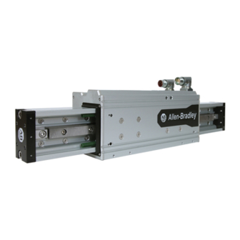
Accessory feet side -mount threaded holes Grease access (not applicable on frame 30) Bottom surface threaded direct-mount holes Stator body ATTENTION: Magnetized tools can cause damage if they come too close to surface magnetic encoder scale tape. Rockwell Automation Publication LDAT-UM001A-EN-P - April 2016... -
Page 15: Catalog Number Explanation
(1) Magnetic strip has 1 mm pole pitch. Final resolution when used with a Kinetix 300 servo drive is 0.488 μm. Absolute encoder is only compatible with Kinetix 300 single-axis drives. Accessories on page 16 for accessory catalog numbers. Rockwell Automation Publication LDAT-UM001A-EN-P - April 2016... -
Page 16: Accessories
Weight, approx g (oz) Foot Mount LDAT-SMID-FTMOUNT 30 (1.06) LDAT-SLARGE-FTMOUNT 40 (1.41) Clevis, Male LDAT-S03-CLVSM 100 (3.53) LDAT-S0507-CLVSM 150 (5.29) LDAT-S1015-CLVSM 370 (13.05) Clevis, Female LDAT-S03-CLVSF 75 (2.65) LDAT-S0507-CLVSF 100 (3.53) LDAT-S1015-CLVSF 250 (8.82) Rockwell Automation Publication LDAT-UM001A-EN-P - April 2016... - Page 17 LDAT-S1015-RODCPLR 1030 (36.33) Horizontal Payload LDAT-S03-HPBRKT 260 (9.17) Mounting Bracket LDAT-S0507-HPBRKT 430 (15.17) LDAT-S10-HPBRKT 910 (32.10) LDAT-S15-HPBRKT 1300 (54.86) Counterbalance Kit LDAT-S03-CBRKT 380 (13.4) LDAT-S0507-CBRKT 600 (21.2) LDAT-S10-CBRKT 950 (33.5) LDAT-S15-CBRKT 1160 (40.9) Rockwell Automation Publication LDAT-UM001A-EN-P - April 2016...
-
Page 18: Replacement Parts
Table 5 - Encoder Replacement Components Cat. No. Description LDAT-TTL-ENC TTL Incremental Encoder LDAT-TTL-SCALE Encoder scale tape, 170 cm (67 in.) Table 6 - Lubrication Accessories Cat. No. Description MPAS-GPUMP Grease pump kit MPAS-CART Grease cartridge Rockwell Automation Publication LDAT-UM001A-EN-P - April 2016... -
Page 19: Installation
Slider has strong magnetic forces. Pinch Point Hazard Ferrous Surface ATTENTION: High force magnets are inside the corrugated cardboard sleeves that cover the sliders. The corrugated sleeves reduce, but do not eliminate magnetic attraction forces. Rockwell Automation Publication LDAT-UM001A-EN-P - April 2016... -
Page 20: Planning Your Installation
Requirements - Teaching Multiple Robots • ANSI/NFPA 79, Electrical Standard for Industrial Machinery • CSA/CAN Z434, Industrial Robots and Robot Systems- General Safety Requirements • EN60204-1, Safety of Machinery. Electrical Equipment of Machines Rockwell Automation Publication LDAT-UM001A-EN-P - April 2016... -
Page 21: Prolonging Linear Thruster Life
If necessary, use extra electrical noise reduction techniques to reduce EMI in noisy environments. See System Design for Control of Electrical Noise Reference Manual, publication GMC-RM001, for more information on reducing the effects of EMI. Rockwell Automation Publication LDAT-UM001A-EN-P - April 2016... -
Page 22: Remove The Linear Thruster From The Shipping Container
5. Lift the linear thruster. 6. Visually inspect for damage. Closely examine the mounting surface, frame, and slider for defects. 7. Notify the carrier of damage from shipping immediately. Rockwell Automation Publication LDAT-UM001A-EN-P - April 2016... -
Page 23: Install The Linear Thruster
Install with Foot Mount Accessory on page 27 None Direct Mount the Linear Thruster on page 27 4. Attach slider-end a accessory to your work load as outlined here. Slider-end accessories are shown on page 16. Rockwell Automation Publication LDAT-UM001A-EN-P - April 2016... -
Page 24: Install Counterbalance Kit
Torque screw to 19.2 N•m (14.2 lb•ft). 3. Screw one 3/8 in. hex nut onto a spring anchor. 4. Install hex nut and spring anchor assemble in one of the three threaded mount locations. Rockwell Automation Publication LDAT-UM001A-EN-P - April 2016... - Page 25 8. Screw one 3/8 in. hex nut onto a spring anchor. 9. Install hex nut and spring anchor assemble in the counter-balance bracket. Torque nut to 33.9 N•m (25.0 lb•ft). Attach your counter-balance spring between the two spring anchor pins. Rockwell Automation Publication LDAT-UM001A-EN-P - April 2016...
-
Page 26: Install With Clevis Mount Accessory
Install the clevis mount accessory with screws included in the kit and torque to the values shown. Cat. No. Clevis Kit Torque, max LDAT-S03 LDAT-03-CLVSM or LDAT-03-CLVSF 6.8 N•m (5.00 lb•ft) LDAT-S05 LDAT-0507-CLVSM or LDAT-0507-CLVSF LDAT-S07 LDAT-S10 LDAT-1015-CLVSM or 14.7 N•m (10.83 lb•ft) LDAT-1015-CLVSF LDAT-S15 Rockwell Automation Publication LDAT-UM001A-EN-P - April 2016... -
Page 27: Install With Foot Mount Accessory
2. Install and evenly tighten the steel fasteners so the linear thruster. Torque the steel fasteners evenly to following values. Cat. No. Torque, max LDAT-S03 4.5 N•m (3.33 lb•in) LDAT-S05 LDAT-S07 LDAT-S10 6.8 N•m (5.00 lb•in) LDAT-S15 Rockwell Automation Publication LDAT-UM001A-EN-P - April 2016... -
Page 28: Build And Route Cables
10 m (32.8 ft). If longer cables are necessary, a 1321-3Rx-x series line reactor is required. See the 1321 Power Conditioning Products Technical Data, publication 1321- TD001, to choose a line reactor for applications that require a cable longer than 10 m (32.8 ft). Rockwell Automation Publication LDAT-UM001A-EN-P - April 2016... -
Page 29: Attach Motor Cables
Failure to observe these safety precautions could result in damage to the linear thruster motor and its components. Rockwell Automation Publication LDAT-UM001A-EN-P - April 2016... -
Page 30: Change Connector Orientation
Do not use tools (for example, pliers and vise-grips) to assist with the rotation of the connector. Failure to observe these safety precautions could result in personal injury or damage to equipment. Rockwell Automation Publication LDAT-UM001A-EN-P - April 2016... -
Page 31: Connector Data
(1) The normally closed thermal switch opens at 100 °C (212 °F). (2) Absolute encoder is only compatible with Kinetix 300 single-axis drives. Figure 7 - Feedback Connector Pinout 11 12 Intercontec P/N AEDC113NN00000202000 Rockwell Automation Publication LDAT-UM001A-EN-P - April 2016... -
Page 32: Power Connector
Failure to observe these safety precautions could result in damage to the motor and its components. Rockwell Automation Publication LDAT-UM001A-EN-P - April 2016... -
Page 33: Required Files
Kinetix 3 2.10 (1) Download Add-on profile for 2198-HSDCK Converter Kit from https://download.rockwellautomation.com/esd/ download.aspx?downloadid=addonprofiles (2) See Kinetix 300 EtherNet/IP Indexing Servo Drives User Manual, publication 2097-UM001. You can use Motion Analyzer software, as required. Rockwell Automation Publication LDAT-UM001A-EN-P - April 2016... -
Page 34: Configure Your Linear Thruster
Positive motion is defined as the slider extend from the stator body opposite Positive Motion Direction the power and feedback connectors. Rockwell Automation Publication LDAT-UM001A-EN-P - April 2016... -
Page 35: Configure And Commission Your Sercos Servo
ATTENTION: Incorrect parameter settings can result in uncontrolled motion, with the potential for damage to the linear thruster. If the Positioning Mode is set to Rotary, damage to the linear thruster or the machine due to incorrect positioning can occur. Rockwell Automation Publication LDAT-UM001A-EN-P - April 2016... -
Page 36: Hookup Test
ATTENTION: Before you tune your linear thruster, read and understand Preventing Undetected and Repetitive High Energy Impacts Prevent Reduced Dynamic Control Performance on page 39 Follow these steps to tune the linear thruster. Rockwell Automation Publication LDAT-UM001A-EN-P - April 2016... -
Page 37: Fine-Tune
Configure Homing Enter these parameters to configure homing for the linear thruster. Parameter Entry/Selection Mode Active Position 0, typical Offset 10 mm Sequence Torque Level-Marker Direction Reverse Bi-directional Rockwell Automation Publication LDAT-UM001A-EN-P - April 2016... -
Page 38: Preventing Undetected And Repetitive High Energy Impacts
When a closed-loop servo system is operating, changes in loads, obstructions, or equipment dynamic response can cause motor capacity to be exceeded. Under these conditions, the Kinetix 6000 and Kinetix 2000 drives fold back the current to the motor to prevent thermal damage. Rockwell Automation Publication LDAT-UM001A-EN-P - April 2016... -
Page 39: Prevent Reduced Dynamic Control Performance
DSL Converter Kit, catalog number 2198- H2DCK, feedback connector. The procedures assume the linear thruster and a servo drive have been installed and wired as one axis of the motion system. Rockwell Automation Publication LDAT-UM001A-EN-P - April 2016... -
Page 40: Configure
ATTENTION: Before you tune your linear thruster, read and understand Preventing Undetected and Repetitive High Energy Impacts Prevent Reduced Dynamic Control Performance on page 39 Follow these steps to tune the linear thruster. 1. Attach your application load to the linear thruster. Rockwell Automation Publication LDAT-UM001A-EN-P - April 2016... -
Page 41: Fine-Tune
Follow these steps to configure your drive for linear thrusters. 1. Loosen the shipping and handling set screw until it is flush with the stator body surface. 2. Run the MotionView software. 3. From the Motor category, click Change Motor. Rockwell Automation Publication LDAT-UM001A-EN-P - April 2016... -
Page 42: Hook Up Test
Follow these steps to tune the linear thruster with an absolute encoder. 1. Attach your application load to the linear thruster. 2. From the General category, set the Drive Mode to Auto Tune. Rockwell Automation Publication LDAT-UM001A-EN-P - April 2016... -
Page 43: Tune With Incremental Encoder
9. To accept the autotune parameters, click Yes Fine-Tune To increase the precision of the positioning of your linear thruster use the Position I-Gain and increase the Position I-Limit to a value > 1. Rockwell Automation Publication LDAT-UM001A-EN-P - April 2016... -
Page 44: Home
Online Drive icon opens in the Workspace. 6. Double-click the Online Drive icon to view the main Drive setup dialog box. 7. From the Workspace, select Motor category. 8. Change the parameter Auto Motor Iden to Disabled. Rockwell Automation Publication LDAT-UM001A-EN-P - April 2016... -
Page 45: Hookup Test
3. Set the parameters to the following values. Parameter Value Motor Direction Bi-Directional Maximum Distance 10,000 counts Step Current 4. Click Start Autotune. The Velocity Regulator Gains changes to reflect autotune values. The Autotune Complete status indicator turns yellow. Rockwell Automation Publication LDAT-UM001A-EN-P - April 2016... -
Page 46: Home
(1) Velocity and kinetic energy can be much higher due to uncontrolled, worst-case motion that is constrained only by the length of stroke and the power capacity of the motor-drive pairing. Rockwell Automation Publication LDAT-UM001A-EN-P - April 2016... -
Page 47: Slider Moving Mass
5.2 (11.57) LDAT-S031030-xxx 4.0 (8.90) LDAT-S033010-xxx 4.0 (8.90) LDAT-S031040-xxx 4.6 (10.23) LDAT-S033020-xxx 4.6 (10.23) LDAT-S032010-xxx 3.4 (7.56) LDAT-S033030-xxx 5.2 (11.57) LDAT-S032020-xxx 4.0 (8.90) LDAT-S033040-xxx 5.9 (12.91) (1) See Slider Moving Mass on page 47 Rockwell Automation Publication LDAT-UM001A-EN-P - April 2016... - Page 48 LDAT-S104040-xxx 21.2 (46.72) LDAT-S102050-xxx 19.2 (42.34) LDAT-S104050-xxx 23.2 (51.09) LDAT-S102060-xxx 21.2 (46.72) LDAT-S104060-xxx 25.2 (55.47) LDAT-S102070-xxx 23.2 (51.09) LDAT-S104070-xxx 27.1 (59.84) LDAT-S102080-xxx 25.2 (55.47) LDAT-S104080-xxx 29.1 (64.22) LDAT-S102090-xxx 27.1 (59.84) LDAT-S104090-xxx 31.1 (68.60) Rockwell Automation Publication LDAT-UM001A-EN-P - April 2016...
- Page 49 LDAT-S156040-xxx 38.4 (84.68) LDAT-S153050-xxx 32.3 (71.30) LDAT-S156050-xxx 41.4 (91.36) LDAT-S153060-xxx 35.4 (77.99) LDAT-S156060-xxx 44.5 (98.05) LDAT-S153070-xxx 38.4 (84.68) LDAT-S156070-xxx 47.5 (104.74) LDAT-S153080-xxx 41.4 (91.36) LDAT-S156080-xxx 50.5 (111.43) LDAT-S153090-xxx 44.5 (98.05) LDAT-S156090-xxx 53.6 (118.12) Rockwell Automation Publication LDAT-UM001A-EN-P - April 2016...
- Page 50 Chapter 4 Commission Notes: Rockwell Automation Publication LDAT-UM001A-EN-P - April 2016...
-
Page 51: Lubrication
Recommended maintenance and lubrication interval for frame 50, 75, 100, and 150 linear thrusters is every 6 months or 5000 km of travel, whichever comes first. Frame 30 linear thrusters are lubricated for life. Rockwell Automation Publication LDAT-UM001A-EN-P - April 2016... -
Page 52: Bearing Cleaning And Lubrication
3. Install the end clamps with the M3 x 0.5 x 6 mm button head cap screws. 4. Install the stator cover with the M3 x 0.5 x 6 mm flat head cap screws. 5. Torque all screws to 1.1 N•m (10 lb•in). Rockwell Automation Publication LDAT-UM001A-EN-P - April 2016... -
Page 53: Strip Cover Cleaning
1. Disassemble the linear thruster by following procedure on page 53. 2. Remove the bearing by following procedure on page 58. 3. Install the bearing by following procedure on page 4. Assemble the linear thruster by following procedure on page Rockwell Automation Publication LDAT-UM001A-EN-P - April 2016... -
Page 54: Replace The Encoder
1. If your linear thruster has the strip cover option, follow Remove Strip Cover procedure on page 59. 2. Loosen the shipping and handling set screw. 3. Remove the coil screws. 4. Remove the bearing screws. Rockwell Automation Publication LDAT-UM001A-EN-P - April 2016... - Page 55 5. Remove the connector side stator end cap. There are five screws on the perimeter of the end cap. 6. Remove the slider end cap opposite the connector side. 7. Remove the end stop bracket. Rockwell Automation Publication LDAT-UM001A-EN-P - April 2016...
- Page 56 ATTENTION: The coil is held to the magnet track on the slider by the magnetic forces. Do not let it move or try to move it while attempting repairs. Moving the coil makes reassembly difficult. Rockwell Automation Publication LDAT-UM001A-EN-P - April 2016...
- Page 57 Slide the slider assembly and verify the cables do not come in contact with it. 15. Attach the stator end cap. 16. If your linear thruster has the strip cover option, install the cover by following the Remove Strip Cover procedure on page in reverse. Rockwell Automation Publication LDAT-UM001A-EN-P - April 2016...
- Page 58 1. Clean the bearing mounting and banking surface with isopropyl alcohol and a soft clean cloth. 2. Loosely install the new bearing rail. 3. Bank the bearing rail against the bearing alignment surface. Rockwell Automation Publication LDAT-UM001A-EN-P - April 2016...
- Page 59 Refer to this figure when removing the strip cover. Top View of LDAT-Series Integrated Linear Thruster (LDAT-S73010xx is shown) Item Description Item Description Stator cover End clamp Stator cover low friction tape Slider cover Stator body low friction tape Rockwell Automation Publication LDAT-UM001A-EN-P - April 2016...
-
Page 60: Remove Encoder
EXAMPLE Use only the proper size and type of driver to remove the encoder bracket screws or you can damage the screw heads 3. Remove the encoder bracket assembly. 4. This exposes the encoder connector. 5. Disconnect the encoder. 6. Remove the encoder from encoder bracket. Rockwell Automation Publication LDAT-UM001A-EN-P - April 2016... -
Page 61: Install The Encoder
Check Encoder 1. Run the Logix Designer application. 2. Click Controller test category. 3. Click Controller tags. 4. Click [+] to expand the axis for you linear thruster. 5. Click Monitor Tags tab. Rockwell Automation Publication LDAT-UM001A-EN-P - April 2016... -
Page 62: Hookup Test
IMPORTANT Lay the stainless steel backer flat to the slider. If the scale is not flat, the encoder scale can rub on the encoder. 5. Remove the paper backing from the encoder scale tape and place the scale tape on the stainless steel backer. Rockwell Automation Publication LDAT-UM001A-EN-P - April 2016... - Page 63 Encoder magnetic strip is damaged Verify function of linear encoder over full range of travel. If a particular location is malfunctioning, replace incremental encoder magnetic scale. If using an absolute encoder, return for repair. Rockwell Automation Publication LDAT-UM001A-EN-P - April 2016...
- Page 64 Kinetix 300 drive displays E07 while using linear thruster Not using correct feedback connector accessory Install un-terminated motor feedback cable with LDAT- with absolute feedback option CONKIT-ABS connector kit Rockwell Automation Publication LDAT-UM001A-EN-P - April 2016...
-
Page 65: Wiring Diagrams
2090-CFBM7DF-CDAFxx (continuous-flex) 2090-CFBM7DF-CDAFxx Continuous flex, SpeedTek for an absolute or incremental encoder 2090-XXNFMF-Sxx Non-flex, threaded DIN, for an absolute or incremental encoder 2090-CFBM4DF-CDAFxx Continuous flex, threaded DIN for an absolute or incremental encoder Rockwell Automation Publication LDAT-UM001A-EN-P - April 2016... - Page 66 GREEN Brown Feedback Motor Feedback WHT/GREEN (MF) Connector GRAY +5VDC Cable WHT/GRAY ECOM Shield ORANGE – Clamp WHT/ORANGE BLUE Thermostat WHT/BLUE YELLOW WHT/YELLOW 2090-XXNFMF-Sxx (standard) or 2090-CFBM7DAFxx (continuous-flex) (flying-lead) Feedback Cable Note 2 Rockwell Automation Publication LDAT-UM001A-EN-P - April 2016...
- Page 67 Same connection as shown DATA- Feedback WHT/GREEN in top figure. GRAY Note 1, 4 ECOM WHT/GRAY +9VDC ORANGE WHT/ORANGE BLUE Thermostat 2090-CFBM7DF-CEAAxx (standard), 2090-CFBM7DD- CEAAxx (standard), 2090-CFBM7DF-CEAFxx (continuous-flex) 2090-CFBM7DD-CEAFxx (continuous-flex) (flying-lead) Feedback Cable Note 3 Rockwell Automation Publication LDAT-UM001A-EN-P - April 2016...
- Page 68 Black WHT/RED Motor Brown GREEN Feedback WHT/GREEN GRAY +5VDC Motor Feedback WHT/GRAY (MF) Connector ECOM ORANGE – WHT/ORANGE BLUE Thermostat WHT/BLUE YELLOW WHT/YELLOW 2090-XXNFMF-Sxx (standard) or 2090-CFBM7DAFxx (continuous-flex) (flying-lead) Feedback Cable Note 2 Rockwell Automation Publication LDAT-UM001A-EN-P - April 2016...
- Page 69 (MP) Connector COS- WHT/RED Black DATA+ GREEN Motor Brown DATA- WHT/GREEN Feedback Motor Feedback GRAY (MF) Connector ECOM WHT/GRAY Cable Shield +9VDC ORANGE Clamp Kit WHT/ORANGE BLUE Thermostat WHT/BLUE 2090-CFBM7DF-CEAAxx (standard, non-flex) 2090-CFBM7DF-CEAFxx (continuous-flex) Rockwell Automation Publication LDAT-UM001A-EN-P - April 2016...
- Page 70 (MP) Connector Brown GREEN Motor WHT/GREEN Motor Feedback Feedback +5VDC GRAY (MF) Connector ECOM WHT/GRAY – ORANGE WHT/ORANGE BLUE Thermostat WHT/BLUE YELLOW WHT/YELLOW 2090-XXNFMF-Sxx (standard) or 2090-CFBM7DAFxx (continuous-flex) (flying-lead) Feedback Cable Note 2 Rockwell Automation Publication LDAT-UM001A-EN-P - April 2016...
-
Page 71: Grounding Techniques For Feedback Cable Shield
Table 17 - Connector Kits for Drive and Linear Thruster Combinations Drive Linear Thruster Encoder Type Use Connector Kit Kinetix 300 Absolute LDAT-CONNKIT-ABS Kinetix 5500 2198-H2DCK Kinetix 300 Incremental 2090-K2CK-D15M Kinetix 2000 Kinetix 6000 2090-K6CK-D15M Ultra3000 2090-UXBB-DM15 Rockwell Automation Publication LDAT-UM001A-EN-P - April 2016... - Page 72 1. Place exposed cable shield in the channel. Exposed Shield Aligned 2. Place the shield clamp over Shield Clamp in the Cable Channel the exposed shield. 3. Tighten screws, torque 0.3 N•m (2.6 lb•in). Rockwell Automation Publication LDAT-UM001A-EN-P - April 2016...
-
Page 73: Index
39 procedures bearing lubrication lubrication access 52 strip cover encoder cleaning 53 replacement 54 replace feedback cables 65 bearing 53 encoder 54 firmware revision 33 encoder scale 54 force of attraction 11 Rockwell Automation Publication LDAT-UM001A-EN-P - April 2016... - Page 74 (AICD) 11 powerful forces 11 wiring diagram Kinetix 2000 drive 68 Kinetix 3 drive 66 Kinetix 300 drive absolute encoder 67 incremental encoder 67 Kinetix 5500 drive 69 Kinetix 6000 drive 70 Ultra3000 71 Rockwell Automation Publication LDAT-UM001A-EN-P - April 2016...
- Page 75 Index Notes: Rockwell Automation Publication LDAT-UM001A-EN-P - April 2016...
- Page 76 Rockwell Automation maintains current product environmental information on its website at http://www.rockwellautomation.com/rockwellautomation/about-us/sustainability-ethics/product-environmental-compliance.page. Allen-Bradley, CompactLogix, ControlLogix, Kinetix, Logix 5000, Rockwell Software, Rockwell Automation, RSlogix 5000, Studio 5000 Logix Designer, and Ultra are trademarks of Rockwell Automation, Inc. Trademarks not belonging to Rockwell Automation are property of their respective companies.
Need help?
Do you have a question about the Allen-Bradley LDAT-S03 Series and is the answer not in the manual?
Questions and answers