Table of Contents
Advertisement
Quick Links
®
SPM
Well Service Pumps & Flow Control Products
QWS 2500 XL Power End
Operation Instruction and Service Manual
Copyright © 2017, S.P.M. Flow Control, Inc.. All rights reserved. S.P.M. Flow Control, Inc. is the owner of the copyright and all confidential information in
this document, which must not be copied in whole or in part, in any form or by any means, and the information in it must not be used for any purpose
other than the specific purpose for which it has been provided without the prior written consent of the copyright owner. SPM, SAFETY IRON, SAFETY
HAMMER, SUR-DROP, DESTINY, STAMPEDE, DURALAST and GLADIATOR are trademarks and/or registered trademarks of S.P.M. Flow Control,
Inc.. WEIR and WEIR (logo) are trademarks and/or registered trademarks of Weir Engineering Services Limited. Certain features of some of the products
disclosed in this document may be protected worldwide by patents pending and registered in the name of S.P.M. Flow Control, Inc..
Document P/N:
2P137414
Release Date:
05/29/2017
Revision:
IR
Advertisement
Table of Contents

Subscribe to Our Youtube Channel
Related Manuals for Weir SPM QWS 2500 XL


Summary of Contents for Weir SPM QWS 2500 XL
- Page 1 HAMMER, SUR-DROP, DESTINY, STAMPEDE, DURALAST and GLADIATOR are trademarks and/or registered trademarks of S.P.M. Flow Control, Inc.. WEIR and WEIR (logo) are trademarks and/or registered trademarks of Weir Engineering Services Limited. Certain features of some of the products disclosed in this document may be protected worldwide by patents pending and registered in the name of S.P.M. Flow Control, Inc..
-
Page 2: Spm ® Product Safety Guide For Well Service Pumps
All images and drawings shown in this document are for representation and illustration purposes only. They may not reflect the actual part/component. The bill of materials and part numbers in this document can change without notification. For details contact Weir Oil & Gas. - Page 3 Weir Oil & Gas for disassembly, inspection and recertification. 6. Welding, brazing, or heating any part of the pump, with the exception of driveline companion flanges, is prohibited. If accessories must be attached, consult Weir Oil & Gas factory prior to installation. ®...
- Page 4 Weir Oil & Gas, can lead to pump damage or failure and SERIOUS INJURY OR DEATH. 2. The pump's fluid end and related piping must always be flushed with clean water after every job. If freezing temperatures are anticipated the fluid cylinder must be completely drained of any fluid.
- Page 5 Weir Oil & Gas for repair and recertification prior to operating again. 6. All fluid cylinders in operation must be disassembled and inspected for cracks. Fluid cylinder inspection should occur on a monthly basis or every 100 hours of operation.
-
Page 6: Table Of Contents
Document P/N: 2P137414 Release Date: 05/29/2017 Revision: TABLE OF CONTENTS ® PRODUCT SAFETY GUIDE FOR WELL SERVICE PUMPS ..............2 SECTION I: GENERAL INFORMATION ......................7 : ......................... 7 SEFUL ORMULAS : ............................ 9 HIPPING AND TORAGE ® QWS 2500 XL P : ....................... -
Page 7: Section I: General Information
Document P/N: 2P137414 Release Date: 05/29/2017 Revision: SECTION I: GENERAL INFORMATION Useful Pump Data Formulas: Definition of Symbols Used: Area (sq. in.) Brake horsepower Barrels per minute (U.S.) Flow velocity (feet per second) Gallons per minute (U.S.) Gallons per revolution (U.S.) Hydraulic horsepower Inside diameter (inches) Mechanical efficiency... - Page 8 Document P/N: 2P137414 Release Date: 05/29/2017 Revision: To calculate the maximum possible pressure at a given rod load when the RL rating and plunger diameter are known: PD x PD x .7854 To calculate the flow in gal/rev or GPM when the plunger diameter, stroke length, and number of cylinders is known: PD x PD x .7854 x SL x NC GPR x RPM...
-
Page 9: Shipping And Storage
Document P/N: 2P137414 Release Date: 05/29/2017 Revision: Shipping and Storage: WARNING: DO NOT HANDLE, LIFT, INSTALL, OPERATE, OR MAINTAIN THIS WELL SERVICE PUMP WITHOUT READING THIS “OPERATION INSTRUCTION AND SERVICE MANUAL” THOROUGLY. TRAINING WITH THESE DOCUMENTS IS A MUST FOR PACKAGERS, OPERATIONS, AND MAINTENANCE PERSONNEL. -
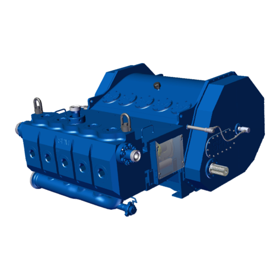
Page 10: Spm ® Qws 2500 Xl Pump Description
Document P/N: 2P137414 Release Date: 05/29/2017 Revision: SECTION II: INSTALLATION AND OPERATION ® QWS 2500 XL Pump Description: ® The SPM QWS 2500 is a reciprocating, positive displacement; horizontal single-acting, quintuplex plunger ® pump which is rated at 2500 Brake Horsepower, input maximum. The SPM QWS 2500 is designed for intermittent duty well service applications such as acidizing, fracturing, well killing, etc. - Page 11 Document P/N: 2P137414 Release Date: 05/29/2017 Revision: ® The SPM QWS 2500 XL power end design and construction details are as follows: Housing Fabricated steel/stress relieved, line bored. Crankshaft Machined from heat treated steel. Precision ground journals. Supported by six heavy-duty cylindrical main roller bearings.
-
Page 12: Performance Data
Document P/N: 2P137414 Release Date: 05/29/2017 Revision: Performance Data: 12 of 44... - Page 13 Document P/N: 2P137414 Release Date: 05/29/2017 Revision: 13 of 44...
- Page 14 Document P/N: 2P137414 Release Date: 05/29/2017 Revision: 14 of 44...
- Page 15 Document P/N: 2P137414 Release Date: 05/29/2017 Revision: 15 of 44...
- Page 16 Document P/N: 2P137414 Release Date: 05/29/2017 Revision: 16 of 44...
- Page 17 Document P/N: 2P137414 Release Date: 05/29/2017 Revision: 17 of 44...
- Page 18 Document P/N: 2P137414 Release Date: 05/29/2017 Revision: 18 of 44...
- Page 19 The mechanical driveline should have a “Diesel Engine Use” torque rating of 20,000 ft. lbs. (96,000 ft. lbs. Short Duration) and should have no less than 1” slip capacity. Weir Oil and Gas recommends a maximum driveline angle of 3 degrees.
-
Page 20: Lifting Requirements
Document P/N: 2P137414 Release Date: 05/29/2017 Revision: Lifting Requirements: ® The fully assembled SPM QWS 2500 XL weighs approximately 16,000 lbs. (7,257 kg) dry, with a standard fluid end and suction manifold. CAUTION: DO NOT MOUNT THE PUMP ON AN INCLINE OR VERTICALLY. ®... -
Page 21: Companion Flange Installation
2P137414 Release Date: 05/29/2017 Revision: Companion Flange Installation: ® Weir Oil & Gas provides the SPM QWS2500 XL pump with one of three options: Keyed companion flange installed on the pinion. Splined companion flange installed on the pinion. - Page 22 Document P/N: 2P137414 Release Date: 05/29/2017 Revision: 22 of 44...
- Page 23 Document P/N: 2P137414 Release Date: 05/29/2017 Revision: 23 of 44...
- Page 24 5. Timken Test rating of 50 lbs. or higher. Cold Temperature Service Power End Lubricant: Weir Oil & Gas highly recommends the use of an extreme pressure gear oil for any plunger pump being used in a cold temperature environment for ambient conditions frequently below 32 F (0 C).
-
Page 25: Power End Lube System Requirements
Document P/N: 2P137414 Release Date: 05/29/2017 Revision: Power End Lube System Requirements: Providing a well-designed trouble-free power end lube system is one of the most important factors in obtaining ® maximum service and long life from the SPM QWS 2500 XL Well Service Plunger Pump. Due to the nature of well servicing operations, the highest pump pressures and highest load conditions typically occur at very slow pump speeds. - Page 26 Document P/N: 2P137414 Release Date: 05/29/2017 Revision: Lube Pump: Must be a gear type pump rated at 50 GPM minimum at its installed maximum engine RPM. Inlet and outlet ports should be as large as possible w/1½” inlet and 3/4” outlet preferred. NOTE: IF THE GEAR PUMP SUCTION INLET PORT IS SMALLER THAN 1½”, A SWAGE CONNECTION SHOULD BE USED ON THE SUCTION PORT IN ORDER TO MAINTAIN A 3”...
- Page 27 180 degrees Fahrenheit. NOTE: UPON REQUEST, WEIR OIL & GAS CAN ASSIST IN PROVIDING LUBE SYSTEM COMPONENTS THAT MEET OR EXCEED THE SPECIFICATIONS NOTED HEREIN. PLEASE CONTACT THE WEIR OIL &...
-
Page 28: Power End Lube System Schematic
Document P/N: 2P137414 Release Date: 05/29/2017 Revision: Power End Lube System Schematic: 28 of 44... -
Page 29: Power End Lube Startup And Performance Data
Document P/N: 2P137414 Release Date: 05/29/2017 Revision: Power End Lube Startup and Performance Data: A properly designed lube system should require adjustments to the system only - at the well service unit’s ® original startup. The following is the SPM recommended guidelines for making the initial adjustments as well as the lube system’s operating specifications. - Page 30 Document P/N: 2P137414 Release Date: 05/29/2017 Revision: Power End Lube System Operating Specifications Power end lube system readings will vary considerably due to the viscosity changes in the gear oil as it warms and thins from a cold startup until it reaches full operating temperature. The system pressure and vacuum variations are caused by the viscosity changes in the oil.
-
Page 31: Tach Drive/Rate Meter Calibration Specifications
Document P/N: 2P137414 Release Date: 05/29/2017 Revision: Tach Drive/Rate Meter Calibration Specifications: PLUNGER *FLUID DISPLACEMENT DIAMETER PER TACH DRIVE REVOLUTION PER TACH DRIVE REVOLUTION @95% V.E. @100% V.E. (MM) 3 3/4 (95.3) 0.2860 0.00681 1.0825 0.3010 0.00717 1.1394 (101.6) 0.3254 0.00775 1.2316 0.3425... -
Page 32: Startup And Break-In Procedure
“wearing in” of various mating parts in the pump itself. The following guidelines have been established by Weir Oil & Gas to minimize startup problems and ensure maximum service from the plunger pump: Inspection Prior to Starting Engine: Check to see that all masking tape, rust preventative, etc. - Page 33 Document P/N: 2P137414 Release Date: 05/29/2017 Revision: Plunger Pump Valve Seating Procedure: In order to protect the fluid cylinder from washing before sustained pumping begins, the tapered valve seats must be pressured up and fully seated creating a positive fluid seal. Adjust the test choke for high pressure/low pump RPM.
- Page 34 Document P/N: 2P137414 Release Date: 05/29/2017 Revision: Adjust the test choke, engine, and transmission to obtain the values in the table below. These settings should be approximately as follows: PLUNGER INPUT SPEED POWER PRESSURE FLOW RATE DIAMETER PINION PUMP (MM) 3 3/4 (95.3) 1350...
- Page 35 Document P/N: 2P137414 Release Date: 05/29/2017 Revision: Adjust the test choke, engine, and transmission to obtain the values in the table below. These settings should be approximately as follows: PLUNGER INPUT SPEED POWER PRESSURE FLOW RATE DIAMETER PINION PUMP (MM) 3 3/4 (95.3) 1801...
-
Page 36: Section Iii: Maintenance And Repair
Document P/N: 2P137414 Release Date: 05/29/2017 Revision: SECTION III: MAINTENANCE AND REPAIR Routine Preventative Maintenance: ® Maximum service and trouble-free operation can be obtained from the SPM well service plunger pump by establishing a thorough preventive maintenance program as follows: During The First 100 Hours of New Pump Operation: ... - Page 37 Document P/N: 2P137414 Release Date: 05/29/2017 Revision: Quarterly (or every 600 hours) Preventive Maintenance (Cont.): Thoroughly clean the power end lube oil suction strainer. Change power end oil filters. Remove and inspect the plungers and packing assembly components. Replace all packing pressure rings and header rings.
-
Page 38: Spm Qws 2500 Duralast Fluid End Removal
Document P/N: 2P137414 Release Date: 05/29/2017 Revision: ® ® QWS 2500 Duralast Fluid End Removal: 1. Disconnect suction and discharge manifolds lines, plunger lube lines and plunger lube check valves, and pressure transducer electrical lines. a) Remove Plunger Clamps using a pneumatic/ratchet wrench and a 3/8" Hex Bit. ®... -
Page 39: Spm ® Qws 2500 Grooved And Grooveless Fluid End Removal
Document P/N: 2P137414 Release Date: 05/29/2017 Revision: ® QWS 2500 Grooved and Grooveless Fluid End Removal: Remove the plunger clamps and separate each plunger from each pony rod as outlined earlier in “To Change Plungers and Packing”. Disconnect the plunger lube hoses and whatever discharge piping connections and suction piping connections are necessary for fluid end removal. -
Page 40: Fluid End Installation Highlights
2P136539). Inspection of the stay rods in the field can determine if a pump has damaged stay rods. Weir recommends that when you replace one stay rod, you replacement them all. You will also find the nut loose, if broken, at the fluid end side of the pump. - Page 41 ® QWS 2500 XL Power End Repair Procedures: Due to the complexity of the task and the need for special tools and training, Weir Oil and Gas does not ® recommend the complete disassembly and major repair of the SPM QWS 2500 XL power end in the field.
-
Page 42: Troubleshooting Guide
Document P/N: 2P137414 Release Date: 05/29/2017 Revision: Troubleshooting Guide: TROUBLE SYMPTOM: PROBABLE CAUSE: Abnormally high vacuum at power 1. Extremely cold ambient temperature/dangerously high end lube pump suction inlet (may oil viscosity. or may not be accompanied by 2. Clogged lube system suction strainer. abnormally low oil pressure). - Page 43 Document P/N: 2P137414 Release Date: 05/29/2017 Revision: TROUBLE SYMPTOM: PROBABLE CAUSE: Plunger and/or packing fluid leak. 1. Packing nut not tightened properly. 2. Worn or damaged packing. 3. Packing installed improperly. 4. Mating seal surface not cleaned properly prior to packing installation.
-
Page 44: Section Iv: Service And Support
HAMMER, SUR-DROP, DESTINY, STAMPEDE, DURALAST and GLADIATOR are trademarks and/or registered trademarks of S.P.M. Flow Control, Inc.. WEIR and WEIR (logo) are trademarks and/or registered trademarks of Weir Engineering Services Limited. Certain features of some of the products disclosed in this document may be protected worldwide by patents pending and registered in the name of S.P.M. Flow Control, Inc..
Need help?
Do you have a question about the SPM QWS 2500 XL and is the answer not in the manual?
Questions and answers