
Related Manuals for Weir ROTO-JET R0


Summary of Contents for Weir ROTO-JET R0
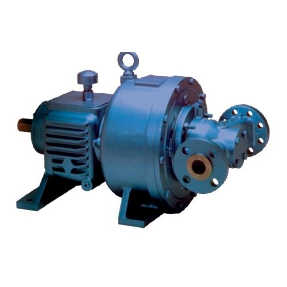
- Page 1 Excellent Engineering Solutions Installation, Operation & Maintenance Manual Model RO, RG, R11, RD11, 2100, 2200 RJ-IOM 03/15...
-
Page 2: Table Of Contents
ROTO-JET PUMP INSTALLATION, OPERATION & MAINTENANCE MANUAL Models RO, RG, R11, RD11, 2100, 2200 Table of Contents GENERAL ....................1 INTRODUCTION ................1 PUMP IDENTIFICATION ..............2 RECEIVING INSPECTION ............. 2 UNLOADING ......................2 STORAGE INSTRUCTIONS ................3 INSTALLATION ..................4 LOCATION OF PUMP .............. - Page 3 ROTO-JET PUMP INSTALLATION, OPERATION & MAINTENANCE MANUAL Models RO, RG, R11, RD11, 2100, 2200 Table of Contents (continued) III. OPERATION .................... 14 OPERATION LIMITS AND DATA ..........14 BEFORE STARTING ..............15 START-UP ..................16 OPERATING CHECKS ..............17 OPERATING CAUTIONS ............. 17 SHUTDOWN .................
- Page 4 ROTO-JET PUMP INSTALLATION, OPERATION & MAINTENANCE MANUAL Models RO, RG, R11, RD11, 2100, 2200 Table of Contents (continued) TROUBLESHOOTING ................25 NO LIQUID DELIVERED .............. 25 NOT ENOUGH LIQUID DELIVERED ..........26 NOT ENOUGH PRESSURE ............27 PUMP OVERLOADS DRIVER ............28 PUMP WORKS FOR AWHILE THEN QUITS .......
-
Page 5: General
ROTO-JET PUMP MODELS RO, RG, R11, RD11, 2100 AND 2200 INSTALLATION, OPERATION AND MAINTENANCE MANUAL WARNING PLEASE STUDY THESE INSTRUCTIONS CAREFULLY BEFORE PUTTING THE PUMP INTO SERVICE. ADHERENCE TO THESE INSTRUCTIONS IS NECESSARY FOR SATISFACTORY START-UP OF YOUR ROTO-JET PUMP. OPERATING PERSONNEL MUST READ AND UNDERSTAND THE START-UP AND OPERATION PARAGRAPHS. -
Page 6: Pump Identification
PUMP IDENTIFICATION Roto-Jet Pumps are described by a series of letters and numbers, such as RGB- S484 or 2100. The first group is the model and indicates the basic mechanical configuration, and the second group, S484, indicates the pick-up tube size. Each pump nameplate will show the pump, model, size, and serial number. -
Page 7: Storage Instructions
WARNING THE EYEBOLT HOLE LOCATED ON THE TOP OF THE PUMP HOUSING IS INTENDED FOR LIFTING THE PUMP ONLY, AND NOT THE COMPLETE PUMP AND BASE PACKAGE. STORAGE INSTRUCTIONS If the pump is not to be installed and operated immediately, store in a clean, dry place. -
Page 8: Installation
INSTALLATION LOCATION OF PUMP Leave sufficient room in front of the pump to remove the manifold for seal replacement. The pump should be located where there is sufficient accessibility for inspection and maintenance. A clear space with ample headroom should be allowed for the use of an overhead crane or hoist sufficiently strong to lift the unit. - Page 9 Adjust the metal wedges, or blocks, around base edge until the base is level. Then suction flanges, discharged flanges and coupling faces should be checked by means of a level. Corrections may be made for flange or coupling level or plumb by shims under the pump or motor.
-
Page 10: Grouting
GROUTING Evenly adjust all anchor bolts, but not too firmly, after first alignment is complete. The baseplate can be grouted to the foundation. On open type baseplates fill the internal spaces with non-shrink grout to the top of the baseplate. For closed type baseplates all the voids under the baseplate must be filled with non-shrink grout. - Page 11 PIPING DIAGRAM Properly sized pressure gauges should be installed in both the inlet and discharge lines. The gauges will allow the operator to easily observe the inlet and discharge pressures of the pump and thereby determine if the pump is operating according to the performance curve.
-
Page 12: Bypass
BYPASS Like other centrifugal type pumps, the Roto-Jet Pump loses a certain amount of power in churning the fluid within the pump. This lost power is converted to heat. If the pump is operated at or near shut-off (no flow), the temperature of the fluid within the pump will rise to unacceptable levels, and could cause seal failure or various other problems. -
Page 13: Filtration
WARNING A VORTEX BREAKER, SCREEN, AND/OR BAFFLE MAY BE REQUIRED IF THE TANK IS SMALL OR THE BYPASS RETURN LINE IS TOO CLOSE TO THE PUMP SUCTION LINE. Block valves are required in the bypass line if the line enters the reservoir below the fluid surface. -
Page 14: Alignment
ALIGNMENT The pump and driver, if supplied, were not aligned at the factory since the unit can shift during shipment. Couplings are disconnected for shipment and belts untensioned. The pump and driver shafts must be checked for angular and parallel alignment. -
Page 15: V-Belt Drive
For coupling parts list and additional installation and maintenance instruction, refer to the Falk Steelflex Coupling Service Manual 428-110, 428-010 or 428-012. Gear Box to Pump Coupling Make: Thomas Type: DBZ-C, size: 226 Pump Shaft: 2-1/4”, Gear Box Shaft: Refer to gear manufacturer’s information. Gap between coupling hub faces to be set at 5”... - Page 16 Sheaves must be aligned so that when a straight edge is held across the face of the driven and driver sheaves there is less than .025” gap between the straight edge and the face of the sheaves. Shafts should be parallel. Always use a matched set of new belts purchased from manufacturer.
-
Page 17: Electric Motor Drive
ELECTRIC MOTOR DRIVE If the pump driver is an electric motor, a motor starter with overload protection must be provided. The overload resets should be set according to local code. Refer to motor nameplate. Direction of rotation of pump shaft must be counterclockwise when facing pump shaft extension. -
Page 18: Operation
RO HIGH SPEED OPERATION RG PUMP RO PUMP 2100 2200 OPTION PARAMETER MAXIMUM MINIMUM MAXIMUM MINIMUM MAXIMUM MINIMUM MAXIMUM MINIMUM MAXIMUM MINIMUM Pump Speed -Direct Connect 6321 RPM 4709 RPM 5443 RPM 4380 RPM 4380 RPM 4380 RPM 4380 RPM 4380 RPM -Belt Drive (12) - Page 19 R11 (2x2) R11 (2 x 1-1/2) RD11 (2x2) RD11 (2x1-1/2) OPERATION PARAMETER MAXIMUM MINIMUM MAXIMUM MINIMUM MAXIMUM MINIMUM MAXIMUM MINIMUM Pump Speed -Direct Connect 3600 RPM 4858 RPM 4858 RPM 4858 RPM -Direct Connect w/ D433 3600 RPM 4380 RPM 4380 RPM 4380 RPM 4858 RPM...
-
Page 20: Before Starting
FOOTNOTES: Consult factory for further information on the following: Materials and seals for charge pressure over 200 psig (14 bar) Specific gravities over 1.2 or below .6. Horsepower in excess of 300 (220 kw) for direct connect and 150 (112kw) for belt drive. - Page 21 WARNING WHEN CHECKING ALIGNMENT, OR PERFORMING ANY WORK ON THE UNITS, ELECTRICAL SERVICE MUST BE LOCKED OUT WITH AN APPROVED LOCKOUT AND KEY. FAILURE TO LOCKOUT EQUIPMENT MAY RESULT IN INJURY. Be sure that all installation requirements have been met and that the system has been designed to keep the pump within its operating limits.
-
Page 22: Start-Up
START-UP WARNING ALL GUARDS AND PROTECTIVE DEVICES MUST BE INSTALLED BEFORE THE PUMP IS STARTED. CONTACT WITH UNGUARDED BELTS, SHEAVES, OR COUPLINGS COULD RESULT IN INJURY. DO NOT OPERATE PUMP WITH BOTH SUCTION AND DISCHARGE VALVES CLOSED OR WITH SUCTION OR DISCHARGE CLOSED BY CLOGGING. THIS COULD CAUSE DAMAGE AND IS DANGEROUS. -
Page 23: Shutdown
All pressure and flow adjustments must be made with the discharge valve; never use a valve on the suction side of the pump for this purpose. Do not operate near shutoff (low flow) without a bypass. Do not operate pump with suction valve closed – this will cause damage and is dangerous. -
Page 24: Iv. Maintenance
Prior to starting the pump follow the steps in Section III, B, “Before Starting”. WARNING WHEN PERFORMING EQUIPMENT MAINTENANCE OR IF THE PUMP IS TO REMAIN OUT OF SERVICE FOR A PERIOD OF TIME, THE EQUIPMENT ELECTRICAL SERVICE MUST BE LOCKED OUT WITH AN APPROVED LOCKOUT AND KEY. -
Page 25: Maintenance Timetable
MAINTENANCE TIMETABLE SCHEDULE MAINTENANCE MAINTENANCE TIME RG, 2100 & RD11 RO, ROH, R11 & 2200 Daily Operating conditions Operating conditions pressure, Flow, Seal pressure, Flow, Seal leakage, Vibration leakage, Vibration – Oil level 1500 hours/3 months; Lubricate bearings 1.oz. whichever occurs first (.03 L). -
Page 26: Strainer
To replace belts: Lockout electrical to motor. Remove belt guard. Slack off belt tension and remove belts. Inspect sheaves for wear or damage. Install new belts.* Replace belt guard. *NOTE: When belts are replaced they must be replaced as a set. STRAINER The filter or strainer in the suction piping should be inspected and cleaned periodically. -
Page 27: Grease Lubricated (Rg, 2100)
Capacity: RO, ROH – Approximately 6 quarts (5.7 L) R11 – Approximately 2 quarts (1.9 L) 2200 – Approximately 4 quarts (3.8 L) Oil change schedule: NOTE: Recommend using a 13/16” 8 point socket to remove the oil drain plugs. See maintenance timetable in Section IV, B. -
Page 28: Bearing System
BEARING SYSTEM Bearings should be inspected for smooth rotation and signs of pitting, rust or metal bluing. Bearings should be replaced as a complete set. The bearing spacer set located between the radial and the thrust bearing is designed to effectively transmit the pump loads to the pedestal. Scoring, rust or debris on the spacer surfaces may affect the life of the bearings. -
Page 29: Operating Maintenance Records
OPERATING MAINTENANCE RECORDS ITEM UNITS DESIGNED ACTUAL VALUE VALUE 1. Pump Speed 2. Pump Discharge Pressure (BAR) Flow (M3/hr) 4. System Pressure (BAR) 5. Inlet Pressure (BAR) 6. Fluid Temperature ° F (° C) DATE MAINTENANCE PERFORMED... -
Page 30: Troubleshooting
TROUBLESHOOTING NO LIQUID DELIVERED AT END DELIVERY POINT OR THROUGH FLOW METER Possible Causes Corrective Action 1. Inlet or discharge valves closed Be sure all valves are fully opened. 2. Lack of prime. Fill pump and suction completely with liquid. Check for vapor bind. -
Page 31: Not Enough Liquid Delivered
NOT ENOUGH LIQUID DELIVERED AT END DELIVERY POINT OR THROUGH FLOW METER Possible Causes Corrective Action 1. Air Leak in Suction Line. Suction line can be tested by shutting off or plugging inlet and putting line under pressure. A gauge will indicate a leak with a drop of pressure. -
Page 32: Not Enough Pressure
NOT ENOUGH PRESSURE ON PRESSURE GAUGE Possible Causes Corrective Action 1. No Restriction on Pump Discharge. Close valve on discharge side at start up. 2. Speed Too Low. Slipping drive belts – check belt tension. Check driver sheave and verify correct size for required speed. Check whether motor is directly across-the-line and receiving full voltage. -
Page 33: Pump Overloads Driver
PUMP OVERLOADS DRIVER Possible Causes Corrective Action 1. Speed too high.. Check driver and verify correct size for required speed. 2. Specific gravity too high. Check. This can cause overloading. 3. Head lower than rating, pumps too much liquid.. Pump may be operating at a higher flow rate than suspected. -
Page 34: Pump Vibration
PUMP VIBRATION Possible Causes Corrective Action 1. Inlet cavitation. In sufficient NPSH (Net Positive Suction Head) available. Available NPSH must always equal or exceed the require NPSH of the pump. Depending on installation: Increase inlet pressure to pump. Reduce inlet pipe friction losses. Increase height of suction vessel. -
Page 35: Liquid Runs From Drain Hole
LIQUID RUNS FROM DRAIN HOLE Possible Causes Corrective Action 1. Seal leaking. Dismantle pump and inspect seal faces. Replace as necessary. 2. Leakage past o-rings. Dismantle pump, clean and inspect o-ring grooves. Inspect o-rings. Replace parts as necessary. NOISE Possible Causes Corrective Action 1. -
Page 36: Ordering Parts
ORDERING PARTS General – It is Roto-Jet Pump’s policy to continually improve its products. Therefore, specifications are subject to change without notice. Parts should be ordered as far in advance or their use as possible since circumstances beyond our control may reduce existing stock. Placing Orders –... - Page 37 For optimum service and technical assistance, please contact our factory for the distributor or representative nearest to your project: Weir Specialty Pumps 440 West 800 South Salt Lake City, UT 84101 (P.O. Box 209, 84110-0209) Tel 801-359-8731 Fax 801-530-7828 info@weirsp.com www.weirpowerindustrial.com...
Need help?
Do you have a question about the ROTO-JET R0 and is the answer not in the manual?
Questions and answers