Table of Contents
Advertisement
Quick Links
- 1 Section I: General Information
- 2 Spm ® Qws 2500 Fluid End Description
- 3 Section II: Installation and Operation
- 4 Installation Highlights
- 5 Routine Preventative Maintenance
- 6 Section III: Maintenance and Repair
- 7 Suction Valve Stop Installation for Grooveless Fluid Ends
- 8 General Information
- Download this manual
®
SPM
Well Service Pumps & Flow Control Products
QWS 2500 Fluid Ends
Operation Instruction and Service Manual
Copyright © 2017, S.P.M. Flow Control, Inc.. All rights reserved. S.P.M. Flow Control, Inc. is the owner of the copyright and all confidential information in
this document, which must not be copied in whole or in part, in any form or by any means, and the information in it must not be used for any purpose
other than the specific purpose for which it has been provided without the prior written consent of the copyright owner. SPM, SAFETY IRON, SAFETY
HAMMER, SUR-DROP, DESTINY, STAMPEDE, DURALAST and GLADIATOR are trademarks and/or registered trademarks of S.P.M. Flow Control,
Inc.. WEIR and WEIR (logo) are trademarks and/or registered trademarks of Weir Engineering Services Limited. Certain features of some of the products
disclosed in this document may be protected worldwide by patents pending and registered in the name of S.P.M. Flow Control, Inc..
Document P/N:
2P136539
Release Date:
05/25/2017
Revision:
F
Advertisement
Table of Contents

Related Manuals for Weir SPM QWS 2500


Summary of Contents for Weir SPM QWS 2500
- Page 1 HAMMER, SUR-DROP, DESTINY, STAMPEDE, DURALAST and GLADIATOR are trademarks and/or registered trademarks of S.P.M. Flow Control, Inc.. WEIR and WEIR (logo) are trademarks and/or registered trademarks of Weir Engineering Services Limited. Certain features of some of the products disclosed in this document may be protected worldwide by patents pending and registered in the name of S.P.M. Flow Control, Inc..
-
Page 2: Spm ® Product Safety Guide For Well Service Pumps
All images and drawings shown in this document are for representation and illustration purposes only. They don’t reflect the actual part/component. The bill of materials and part numbers in this document can change without notification. For details contact Weir Oil & Gas. - Page 3 Weir Oil & Gas for disassembly, inspection and recertification. 6. Welding, brazing, or heating any part of the pump, with the exception of driveline companion flanges, is prohibited. If accessories must be attached, consult Weir Oil & Gas factory prior to installation. ®...
- Page 4 . Failure to do so may Only SPM replacement parts should be utilized result in loss of warranty as well as SERIOUS INJURY OR DEATH. Weir Oil & Gas provides a Pump Maintenance Mechanic Training School to qualify pump service mechanics. ®...
- Page 5 Weir Oil & Gas for repair and recertification prior to operating again. 6. All fluid cylinders in operation must be disassembled and inspected for cracks. Fluid cylinder inspection should occur on a monthly basis or every 100 hours of operation.
-
Page 6: Table Of Contents
2P136539 Document P/N: Release Date: 05/25/2017 Revision: TABLE OF CONTENTS ® PRODUCT SAFETY GUIDE FOR WELL SERVICE PUMPS ..................2 SECTION I: GENERAL INFORMATION ..........................7 : ............................. 7 SEFUL ORMULAS : ................................ 9 HIPPING AND TORAGE ... -
Page 7: Section I: General Information
2P136539 Document P/N: Release Date: 05/25/2017 Revision: SECTION I: GENERAL INFORMATION Useful Pump Data Formulas: Definition of Symbols Used: Area (sq. in.) Brake horsepower Barrels per minute (U.S.) Flow velocity (feet per second) Gallons per minute (U.S.) Gallons per revolution (U.S.) Hydraulic horsepower Inside diameter (inches) Mechanical efficiency... - Page 8 2P136539 Document P/N: Release Date: 05/25/2017 Revision: To calculate the flow in gal/rev or GPM when the plunger diameter, stroke length, and number of cylinders is known: PD x PD x .7854 x SL x NC GPR x RPM ...
-
Page 9: Shipping And Storage
2P136539 Document P/N: Release Date: 05/25/2017 Revision: Shipping and Storage: WARNING: DO NOT HANDLE, LIFT, INSTALL, OPERATE, OR MAINTAIN THIS WELL SERVICE FLUID END WITHOUT READING THIS “OPERATION INSTRUCTION AND SERVICE MANUAL” THOROUGLY. TRAINING WITH THESE DOCUMENTS IS A MUST FOR PACKAGERS, OPERATIONS, AND MAINTENANCE PERSONNEL. -
Page 10: Section Ii: Installation And Operation
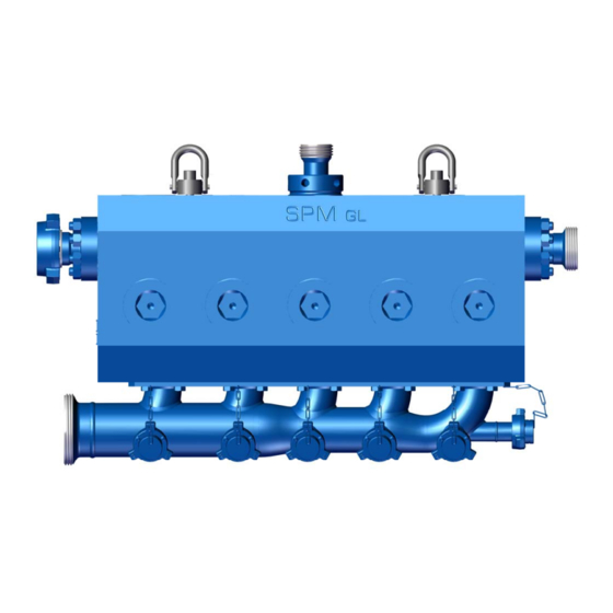
2P136539 Document P/N: Release Date: 05/25/2017 Revision: SECTION II: INSTALLATION AND OPERATION ® QWS 2500 Fluid End Description: ® The SPM QWS 2500 is a reciprocating, positive displacement; horizontal single-acting, quintuplex plunger ® pump which is rated at 2500 Brake Horsepower, input maximum. The SPM QWS 2500 is designed for intermittent duty well service applications such as acidizing, fracturing, well killing, etc. - Page 11 2P136539 Document P/N: Release Date: 05/25/2017 Revision: ® The SPM QWS 2500 fluid end design and construction details are as follows: Fluid Cylinder Durable low maintenance “Valve Over Valve” monoblock design. Precision machined from high strength heat- treated alloy steel forgings or stainless steel. Plungers “Quick Disconnect”...
-
Page 12: Installation Highlights
Inspection of the stay rods in the field can determine if a pump has damaged stay rods. Weir recommends that when you replace one stay rod, you replacement them all. You will also find the nut loose, if broken, at the fluid end side of the pump. - Page 13 2P136539 Document P/N: Release Date: 05/25/2017 Revision: Torquing of bolts/ nuts should be done in a cross-bolting pattern sequence. Use sequence shown below. First torque to 1/3 of full torque, then to 2/3 torque. Repeat full torque sequence until bolts/ nuts cease to move. 1/3 TORQUE 2/3 TORQUE FULL TORQUE...
- Page 14 2P136539 Document P/N: Release Date: 05/25/2017 Revision: Lifting Requirements: ® The SPM QWS 2500 fluid end weighs approximately 4,804 pounds (2179 kg) dry, fully assembled with a standard fluid end and suction manifold. CAUTION: DO NOT MOUNT THE PUMP ON AN INCLINE OR VERTICALLY. ®...
-
Page 15: Plunger Lube System Requirements
After filling with the proper grade of Rock Drill oil, and before rotating the well service plunger pump, the lube system should be adjusted to supply oil to each plunger and packing assembly. Weir Oil & Gas recommends a minimum of 1 pint per plunger per hour for adequate packing ® lubrication. Results from SPM internal tests support this although variables in packaging and field operations may result in higher consumption rates. -
Page 16: Recommended Plunger Lube Oils
Oil & Gas highly recommends the use of a modern “Rock Drill” for improved lubrication of the plungers and packing. If “Rock Drill” is not available, a suitable “Way Oil” or “Leader Valve Oil” may be substituted. Weir Oil & Gas recommends the use of Rock Drill or Way Oil that meet the following specifications: ISO Grade API Gravity 29.4... -
Page 17: Recommended Plunger Grease Lube System
MUST be flipped in the packing nut to allow a path for the excess grease to escape the packing bore chamber. Weir Oil & Gas recommends the use of a double or triple “ought” grease, 00 or 000. -
Page 18: Plunger Lube Circuit Diagram
2P136539 Document P/N: Release Date: 05/25/2017 Revision: Plunger Lube Circuit Diagram: 18 of 42... -
Page 19: Supercharging System Requirements
2P136539 Document P/N: Release Date: 05/25/2017 Revision: Supercharging System Requirements: Due to the high-speed design characteristics associated with well service plunger pumps, supercharging the ® well service fluid end is necessary. The nature of well service operations (extreme variations in flow rates coupled with the pumping of heavy slurries) requires a well-designed supercharge system. - Page 20 2P136539 Document P/N: Release Date: 05/25/2017 Revision: Secondary Suction Piping and Hoses: These are defined as the piping that carries fluid under pressure from the discharge of the centrifugal pump to ® another point in the system. This is the piping which connects the centrifugal charge pump to the SPM plunger pump suction inlet and can also be the piping which connects the centrifugal mixing pump’s discharge to a mixing tub inlet.
-
Page 21: Supercharging System Operational Parameters
2P136539 Document P/N: Release Date: 05/25/2017 Revision: Supercharging System Operational Parameters: The recommended Supercharge Pressure at the plunger pump suction inlet is 80 PSI (185 feet head) minimum to 100 PSI (230 feet head) maximum. NOTE: THE SUPERCHARGE PRESSURE MUST ALWAYS BE GREATER THAN THE VAPOR PRESSURE OF THE FLUID BEING PUMPED. - Page 22 Fig. 3 illustrates how a supplementary device can be added to allow fluid supply to both ends of the manifold. The zoomie style manifold is illustrated in Fig. 4. Contact Weir Oil & Gas engineering for more material on these two styles. 22 of 42...
- Page 23 2P136539 Document P/N: Release Date: 05/25/2017 Revision: 23 of 42...
- Page 24 2P136539 Document P/N: Release Date: 05/25/2017 Revision: 24 of 42...
-
Page 25: Startup And Break-In Procedures
2P136539 Document P/N: Release Date: 05/25/2017 Revision: Startup and Break-In Procedures: Please refer to the SPM ® QWS 2500 power end operation and service manual. 25 of 42... - Page 26 In the oil field, it is paramount to have proper replacement packing sets readily available that are suited for your specific application. At Weir Oil & Gas, we understand this, and have restructured our packing offering to better meet your needs.
- Page 27 THEIR DISCRETION, THE PLUNGER PACKING WIPER RING MUST BE FLIPPED IN THE PACKING NUT TO ALLOW A PATH FOR THE EXCESS GREASE TO ESCAPE THE PACKING BORE CHAMBER. WEIR OIL & GAS RECOMMENDS THE USE OF A DOUBLE OR TRIPLE “OUGHT” GREASE; 00 OR 000.
-
Page 28: Section Iii: Maintenance And Repair
2P136539 Document P/N: Release Date: 05/25/2017 Revision: SECTION III: MAINTENANCE AND REPAIR: Routine Preventative Maintenance: ® Maximum service and trouble-free operation can be obtained from the SPM well service fluid end by establishing a thorough preventive maintenance program as follows: During The First 100 Hours of New Pump Operation: ... - Page 29 2P136539 Document P/N: Release Date: 05/25/2017 Revision: Yearly (or as required) Preventive Maintenance: Replace worn plungers and packing brass. Replace worn or corroded valve covers, suction valve stops, packing nuts, discharge flanges, pump tools, etc. Replace all discharge flange seals and suction manifold seals. ...
- Page 30 2P136539 Document P/N: Release Date: 05/25/2017 Revision: Expendable Components (Cont.): b. Fluid End Fluid Ends commonly fail by cracking in the crossbore. The time of failure can be extended by a properly sized suction stabilizer. If it is a nitrogen bladder type, check the charge pressure before each job.
-
Page 31: Roubleshooting Uide
2P136539 Document P/N: Release Date: 05/25/2017 Revision: Troubleshooting Guide: TROUBLE SYMPTOM: PROBABLE CAUSE: Suction hose(s) jumping. 1. Possible bad suction valve. 2. Confirm the valves in the piping are completely open. 3. The pump has been completely primed. 4. Suction seat (s) could be damaged. Suction or discharge caps leaking. - Page 32 2P136539 Document P/N: Release Date: 05/25/2017 Revision: TROUBLE SYMPTOM: PROBABLE CAUSE: Fluid knock or hammer. 1. Air entering supercharge system through loose, worn or damaged connections. 2. Air entering supercharge system through leaking charge pump seals. 3. Fluid being pumped contains gas or vapor. 4.
-
Page 33: Spm
2P136539 Document P/N: Release Date: 05/25/2017 Revision: ® QWS 2500 Fluid End Repair Procedures: To remove Valves and seats: ® Using the SPM 2” hex cover wrench and a 6 pound Hammer, remove the suction and discharge cover retainer nuts from the fluid cylinder. ®... - Page 34 2P136539 Document P/N: Release Date: 05/25/2017 Revision: To Change Plungers and Packing: Using a 3/8” hex key wrench, remove the two 1/2” socket head capscrews from each of the plunger clamps. Separate the two halves of each plunger clamp and remove them being careful to keep them in matched pairs.
- Page 35 2P136539 Document P/N: Release Date: 05/25/2017 Revision: To Remove Discharge Flanges: Using a 1⅝” wrench, remove the 1” nuts from each of the two discharge flanges. Remove each discharge flange from the fluid cylinder. Remove the fluid seals from both the inlet side and outlet side of each discharge flange.
- Page 36 2P136539 Document P/N: Release Date: 05/25/2017 Revision: To Remove The Fluid End: Remove the plunger clamps and separate each plunger from each pony rod as outlined earlier in “To Change Plungers and Packing”. Disconnect the plunger lube hoses and whatever discharge piping connections and suction piping connections are necessary for fluid end removal.
-
Page 37: Suction Valve Stop Installation For Grooveless Fluid Ends
2P136539 Document P/N: Release Date: 05/25/2017 Revision: Suction Valve Stop Installation for Grooveless Fluid Ends: The following instructions show the correct method of installing suction valve stops in the “Grooveless” style fluid cylinders; first introduced in 2004. 1. Insert the valve stop with its base (opposite the eye) pointing towards the power end. The eye of the stop must be closest to the suction cover side of the fluid cylinder. - Page 38 2P136539 Document P/N: Release Date: 05/25/2017 Revision: 2. Angle the valve stop with the forward edge of the base pointing downward while compressing the valve spring. Catch the base inside the bottle bore of the fluid cylinder; as shown in Fig. 2. Figure 2 3.
- Page 39 2P136539 Document P/N: Release Date: 05/25/2017 Revision: 4. Rotate the rear of the base into a level position in the bottle bore as shown in Fig. 4. The valve stop tool may be placed in the eye of the stop to assiste in rotating the stop into position (see Fig. 3). A slight push after rotating the bar stock will help push the rear lip past the bore edge.
- Page 40 2P136539 Document P/N: Release Date: 05/25/2017 Revision: 8. Align valve stop “eye” with the post on the suction cover. For initial aligning, use the suction cover without the seal installed. Guide the suction cover into the bore using a slide hammer rod and verify that the cover post has engaged the valve stop eye.
-
Page 41: Suction Valve Stop Installation For Grooved Fluid Ends
2P136539 Document P/N: Release Date: 05/25/2017 Revision: Suction Valve Stop Installation for Grooved Fluid Ends: 1. To insert valves, valve seats, and springs; Follow instructions in the “To remove valves and seats” section of this manual. 2. Insert valve stop and turn valve stop approximately 90 degrees. Ensure that it is properly seated in the grooves in the cylinder and that it is turned perpendicular to the plunger. -
Page 42: Section Iv: Service And Support
HAMMER, SUR-DROP, DESTINY, STAMPEDE, DURALAST and GLADIATOR are trademarks and/or registered trademarks of S.P.M. Flow Control, Inc.. WEIR and WEIR (logo) are trademarks and/or registered trademarks of Weir Engineering Services Limited. Certain features of some of the products disclosed in this document may be protected worldwide by patents pending and registered in the name of S.P.M. Flow Control, Inc..
Need help?
Do you have a question about the SPM QWS 2500 and is the answer not in the manual?
Questions and answers