Table of Contents
Advertisement
®
SPM
Well Service Pumps & Flow Control Products
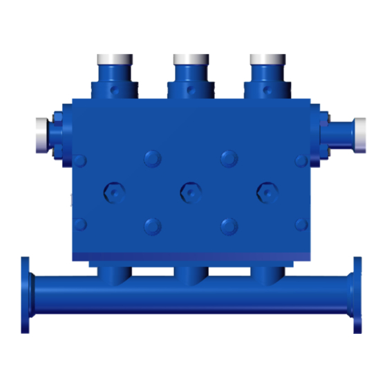
TWS600S Fluid End
Operation Instruction and Service Manual
Service manuals 2P121260 and 2P121262 replace 4P105066, and revision E supersedes all previous versions
Copyright © 2017, S.P.M. Flow Control, Inc.. All rights reserved. S.P.M. Flow Control, Inc. is the owner of the copyright and all confidential information in
this document, which must not be copied in whole or in part, in any form or by any means, and the information in it must not be used for any purpose
other than the specific purpose for which it has been provided without the prior written consent of the copyright owner. SPM, SAFETY IRON, SAFETY
HAMMER, SUR-DROP, DESTINY, STAMPEDE, DURALAST and GLADIATOR are trademarks and/or registered trademarks of S.P.M. Flow Control,
Inc.. WEIR and WEIR (logo) are trademarks and/or registered trademarks of Weir Engineering Services Limited. Certain features of some of the products
disclosed in this document may be protected worldwide by patents pending and registered in the name of S.P.M. Flow Control, Inc..
Document P/N:
2P121260
Release Date:
02/27/2017
Revision:
E
Advertisement
Table of Contents

Subscribe to Our Youtube Channel
Related Manuals for Weir SPM TWS600S


Summary of Contents for Weir SPM TWS600S
- Page 1 HAMMER, SUR-DROP, DESTINY, STAMPEDE, DURALAST and GLADIATOR are trademarks and/or registered trademarks of S.P.M. Flow Control, Inc.. WEIR and WEIR (logo) are trademarks and/or registered trademarks of Weir Engineering Services Limited. Certain features of some of the products disclosed in this document may be protected worldwide by patents pending and registered in the name of S.P.M. Flow Control, Inc..
- Page 2 All images and drawings shown in this document are for representation and illustration purposes only. They don’t reflect the actual part/component. The bill of materials and part numbers in this document can change without notification. For details contact Weir Oil & Gas.
- Page 3 Weir Oil & Gas for disassembly, inspection and recertification. 6. Welding, brazing, or heating any part of the pump, with the exception of driveline companion flanges, is prohibited. If accessories must be attached, consult Weir Oil & Gas factory prior to installation. ®...
- Page 4 Weir Oil & Gas, can lead to pump damage or failure and SERIOUS INJURY OR DEATH. 2. The pump's fluid end and related piping must always be flushed with clean water after every job. If freezing temperatures are anticipated the fluid cylinder must be completely drained of any fluid.
- Page 5 Weir Oil & Gas for repair and recertification prior to operating again. 6. All fluid cylinders in operation must be disassembled and inspected for cracks. Fluid cylinder inspection should occur on a monthly basis or every 100 hours of operation.
-
Page 6: Table Of Contents
2P121260 Document P/N: Release Date: 02/27/2017 Revision: TABLE OF CONTENTS SECTION I: GENERAL INFORMATION ..........................7 : ............................. 7 SEFUL ORMULAS : ................................ 9 HIPPING AND TORAGE SECTION II: INSTALLATION AND OPERATION ......................... 10 ®... -
Page 7: Section I: General Information
2P121260 Document P/N: Release Date: 02/27/2017 Revision: SECTION I: GENERAL INFORMATION Useful Pump Data Formulas: Definition of Symbols Used: Area (sq. in.) Brake horsepower Barrels per minute (U.S.) Flow velocity (feet per second) Gallons per minute (U.S.) Gallons per revolution (U.S.) Hydraulic horsepower Inside diameter (inches) Mechanical efficiency... - Page 8 2P121260 Document P/N: Release Date: 02/27/2017 Revision: To calculate the flow in gal/rev or GPM when the plunger diameter, stroke length, and number of cylinders is known: PD x PD x .7854 x SL x NC GPR x RPM ...
-
Page 9: Shipping And Storage
2P121260 Document P/N: Release Date: 02/27/2017 Revision: Shipping and Storage: WARNING: DO NOT HANDLE, LIFT, INSTALL, OPERATE, OR MAINTAIN THIS WELL SERVICE PUMP WITHOUT READING THIS “OPERATION INSTRUCTION AND SERVICE MANUAL” THOROUGLY. TRAINING WITH THESE DOCUMENTS IS A MUST FOR PACKAGERS, OPERATIONS, AND MAINTENANCE PERSONNEL. -
Page 10: Section Ii: Installation And Operation
® TWS600S Pump Description: The SPM TWS600S is a reciprocating, positive displacement, horizontal single-acting, triplex plunger pump that is rated at 600 Brake Horsepower input maximum. The TWS600S is designed for intermittent duty well service applications such as acidizing, cementing, fracturing, well killing, gravel packing, etc. - Page 11 2P121260 Document P/N: Release Date: 02/27/2017 Revision: Fluid Cylinder Low maintenance “Valve Over Valve” monoblock design. Precision machined from high strength one-piece alloy steel forging. Plungers Machined from steel w/precision ground hard overlay (60 Rc) acid resistant packing surface. Plunger Packing “Self-adjusting”...
-
Page 12: Installation Highlights
2P121260 Document P/N: Release Date: 02/27/2017 Revision: Installation Highlights: The proper installation of your SPM well service pump is a must in obtaining long life and trouble free service. Particular attention must be given to the following items: Power Source: The prime mover (usually a 2100 RPM diesel engine) should not be rated at more than 725 BHP intermittent service in order to avoid overpowering the pump. - Page 13 2P121260 Document P/N: Release Date: 02/27/2017 Revision: Plunger Lubrication: ® well service plunger pumps require a force fed oil plunger lube system. The unit is internally and externally plumbed so that the correct oil source provided by the customer will supply lube to all appropriate surfaces.
-
Page 14: Lifting Requirements
2P121260 Document P/N: Release Date: 02/27/2017 Revision: Lifting Requirements: ® The SPM TWS600S fluid end assembly with suction manifold weighs approximately 1,700 Lbs./ 771 Kg. CAUTION: DO NOT MOUNT THE PUMP ON AN INCLINE OR VERTICALLY. ® WARNING: LIFTING THE SPM TWS600S PUMP AND/OR FLUID END WITHOUT USING EQUIPMENT RATED FOR THIS LOAD CAN CAUSE EQUIPMENT DAMAGE, PERSONAL INJURY OR DEATH. - Page 15 Weir Oil & Gas recommends a minimum of 1 pint per plunger per hour for adequate packing ® lubrication. Results from SPM internal tests support this although variables in packaging and field operations may result in higher consumption rates.
-
Page 16: Recommended Plunger Lube Oils
Oil & Gas highly recommends the use of a modern “Rock Drill” for improved lubrication of the plungers and packing. If “Rock Drill” is not available, a suitable “Way Oil” may be substituted. Weir Oil & Gas recommends the use of Rock Drill or Way Oil that meet the following specifications: ISO Grade API Gravity 29.4... -
Page 17: Recommended Plunger Grease Lube System
MUST be flipped in the packing nut to allow a path for the excess grease to escape the packing bore chamber. Weir Oil & Gas recommends the use of a double or triple “ought” grease, 00 or 000. -
Page 18: Plunger Lube Circuit Diagram
2P121260 Document P/N: Release Date: 02/27/2017 Revision: Plunger Lube Circuit Diagram: 18 of 41... -
Page 19: Supercharging System Requirements
2P121260 Document P/N: Release Date: 02/27/2017 Revision: Supercharging System Requirements: Due to the high-speed design characteristics associated with well service plunger pumps, supercharging the ® well service pump is necessary. The nature of well service operations (extreme variations in flow rates coupled with the pumping of heavy slurries) requires a well-designed supercharge system. - Page 20 2P121260 Document P/N: Release Date: 02/27/2017 Revision: Secondary Suction Piping and Hoses: These are defined as the piping that carries fluid under pressure from the discharge of the centrifugal pump to ® another point in the system. This is the piping which connects the centrifugal charge pump to the SPM plunger pump suction inlet and can also be the piping which connects the centrifugal mixing pump’s discharge to a mixing tub inlet.
-
Page 21: Supercharging System Operational Parameters
2P121260 Document P/N: Release Date: 02/27/2017 Revision: Supercharging System Operational Parameters: The recommended Supercharge Pressure at the plunger pump suction inlet is 80 PSI (185 feet head) minimum to 100 PSI (230 feet head) maximum. NOTE: THE SUPERCHARGE PRESSURE MUST ALWAYS BE GREATER THAN THE VAPOR PRESSURE OF THE FLUID BEING PUMPED. -
Page 22: Recommended Practice For Pump Packing
2P121260 Document P/N: Release Date: 02/27/2017 Revision: Recommended Practice for Pump Packing: ® Well Service Pump Packing ® For use in the SPM TWS 600S and QWS 1000S pumps for cementing, acidizing, and other well service applications. This offering is rated up to 15,000 psi. ... - Page 23 2P121260 Document P/N: Release Date: 02/27/2017 Revision: Tach Drive/Rate Meter Calibration Specifications: PLUNGER *FLUID DISPLACEMENT DIAMETER PER TACH DRIVE REVOLUTION PER TACH DRIVE REVOLUTION @95% V.E. @100% V.E. (MM) 2 1/2 (63.5) 0.0727 0.00173 0.2751 0.0765 0.00182 0.2896 2 3/4 (69.9) 0.0879 0.00209...
-
Page 24: Startup And Break-In Procedure
2P121260 Document P/N: Release Date: 02/27/2017 Revision: Startup and Break-In Procedure: Each new pump must undergo a brief but thorough startup and break-in procedure in order to verify the field worthiness of the unitized pumping system and in order to allow a gradual “wearing in” of various mating parts in the pump itself. - Page 25 2P121260 Document P/N: Release Date: 02/27/2017 Revision: Plunger Pump Valve Seating Procedure: In order to protect the fluid cylinder from washing before sustained pumping begins, the tapered valve seats must be pressured up and fully seated creating a positive fluid seal. Adjust the test choke for high pressure/low pump RPM.
- Page 26 2P121260 Document P/N: Release Date: 02/27/2017 Revision: Adjust the test choke, engine, and transmission according to the values below. These settings should be approximately as follows: PLUNGER INPUT SPEED POWER PRESSURE FLOW RATE DIAMETER PINION PUMP (MM) 2 1/2 (63.5) 227.4 5129 35.4...
- Page 27 Remove the power end lube system magnet and inspect for any unusually large particles of metal. Change the lube oil filters. __________________________________________________ Pressure is limited to 15,000 PSI due to discharge flange and plunger configuration. For higher pressure, contact Weir Oil & Gas engineering department. 27 of 41...
-
Page 28: Section Iii: Maintenance And Repair
2P121260 Document P/N: Release Date: 02/27/2017 Revision: SECTION III: MAINTENANCE AND REPAIR: Routine Preventative Maintenance: ® Maximum service and trouble-free operation can be obtained from the SPM well service plunger pump by establishing a thorough preventive maintenance program as follows: During The First 100 Hours of New Pump Operation: ... - Page 29 2P121260 Document P/N: Release Date: 02/27/2017 Revision: Quarterly (or every 600 hours) Preventive Maintenance (Cont.): Change power end filters. Remove and inspect the plungers and packing assembly components. Replace all packing pressure rings and header rings. Clean the plunger pump’s oil breather and the power end lube oil reservoir breather. ...
- Page 30 2P121260 Document P/N: Release Date: 02/27/2017 Revision: Expendable Components (Cont.): b. Fluid End Fluid Ends commonly fail by cracking in the crossbore. The time of failure can be extended by a properly sized suction stabilizer. If it is a nitrogen bladder type, check the charge pressure before each job.
-
Page 31: Troubleshooting Guide
2P121260 Document P/N: Release Date: 02/27/2017 Revision: Troubleshooting Guide: TROUBLE SYMPTOM: PROBABLE CAUSE: Abnormally high vacuum at power 1. Extremely cold ambient temperature/dangerously high end lube pump suction inlet (may oil viscosity. or may not be accompanied by 2. Clogged lube system suction strainer. abnormally low oil pressure). - Page 32 2P121260 Document P/N: Release Date: 02/27/2017 Revision: TROUBLE SYMPTOM: PROBABLE CAUSE: Plunger and/or packing fluid leak. 1. Packing nut not tightened properly. 2. Worn or damaged packing. 3. Packing installed improperly. 4. Mating seal surface not cleaned properly prior to packing installation.
-
Page 33: Spm ® Tws600S Fluid End Repair Procedures
2P121260 Document P/N: Release Date: 02/27/2017 Revision: ® TWS600S Fluid End Repair Procedures: To remove Valves and Seats: ® Using the SPM 2” hex cover wrench and a 10lb. hammer, remove the suction covers and discharge covers from the fluid cylinder. Turn the suction valve stops approximately 90 degrees and remove them from the fluid cylinder along with the valve springs underneath them. - Page 34 2P121260 Document P/N: Release Date: 02/27/2017 Revision: To Change Plungers and Packing: Remove the plunger lube fitting from each packing nut. ® Using the SPM packing nut tool, loosen each of the packing nuts at least one full turn. Remove the suction covers as outlined earlier in “To Remove Valves & Seats”. ®...
- Page 35 2P121260 Document P/N: Release Date: 02/27/2017 Revision: To Remove Discharge Flanges: Using a 1⅝” wrench, remove the four 1” nuts from each of the two discharge flanges. Remove each discharge flange from the fluid cylinder. Remove the fluid seals from both the inlet side and outlet side of each discharge flange.
- Page 36 2P121260 Document P/N: Release Date: 02/27/2017 Revision: To Remove The Fluid End: ® Disconnect the plunger from the crosshead using the SPM plunger wrench as outlined earlier in Section B “To Change Plunger and Packing”. Disconnect the plunger lube hoses and whatever discharge piping connections and suction piping connections are necessary for fluid end removal.
-
Page 37: Suction Valve Stop Installation For Grooved Fluid Ends
2P121260 Document P/N: Release Date: 02/27/2017 Revision: Suction Valve Stop Installation for Grooved Fluid Ends: 1. To insert valves, valve seats, and springs; Follow instructions in the “To remove valves and seats” section of this manual. 2. Insert valve stop and turn valve stop approximately 90 degrees. Ensure that it is properly seated in the grooves in the cylinder and that it is turned perpendicular to the plunger. - Page 38 2P121260 Document P/N: Release Date: 02/27/2017 Revision: ® 5. Using the SPM hex cover wrench and 6 pound hammer, reinstall the discharge and suction cover retainer nuts per instructions in the “to remove valves and seats” section of this manual. (Typically two or three blows with the hammer will seat the cap and nut).
-
Page 39: Section Iv: Service And Support
HAMMER, SUR-DROP, DESTINY, STAMPEDE, DURALAST and GLADIATOR are trademarks and/or registered trademarks of S.P.M. Flow Control, Inc.. WEIR and WEIR (logo) are trademarks and/or registered trademarks of Weir Engineering Services Limited. Certain features of some of the products disclosed in this document may be protected worldwide by patents pending and registered in the name of S.P.M. Flow Control, Inc.. -
Page 40: Spare Parts And Usages
2P121260 Document P/N: Release Date: 02/27/2017 Revision: Spare Parts and Usages Item Description Quantity Replacement Insert, Valve 24 Days Valve 24 Days or AR Seat 24 Days or AR Seal, O-ring for seat As Required Spring, Valve 180 Days Packing, Complete As Required Packing, Soft Set 45 Days or AR... -
Page 41: Fluid End Drawings
2P121260 Document P/N: Release Date: 02/27/2017 Revision: Fluid End Drawings: 41 of 41...
Need help?
Do you have a question about the SPM TWS600S and is the answer not in the manual?
Questions and answers