Table of Contents
Advertisement
Quick Links
Megger Head Office
Megger Limited
Archcliffe Road Dover Kent
CT17 9EN
ENGLAND
T:
+44 (0)1 304 502101
F.
+44 (0)1 304 207342
Manufacturing Sites
Megger Limited
Archcliffe Road
Dover
Kent
T:
+44 (0)1 304 502101
F:
+44 (0)1 304 207342
Megger USA - Dallas
4271 Bronze Way
Dallas TX 75237-1019
USA
T:
+1 800 723 2861 (USA only)
T:
+1 214 333 3201
F:
+1 214 331 7399
E:
ussales@megger.com
This instrument is manufactured in the United States.
The company reserves the right to change the specification or design without prior notice.
Megger is a registered trademark.
© Megger Limited 2018
Megger GmbH
Obere Zeil 2 61440
Oberursel,
GERMANY
T:
06171-92987-0
F:
06171-92987-19
Megger AB
Rinkebyvägen 19, Box 724,
SE-182 17
DANDERYD
T:
08 510 195 00
E:
seinfo@megger.com
Megger USA - Valley Forge
Valley Forge Corporate Center
2621 Van Buren Avenue
Norristown
Pennsylvania, 19403
USA
T:
1-610 676 8500
F:
1-610-676-8610
Megger Baker Instruments
4812 McMurry Avenue, Suite 100
Fort Collins, CO 80525
USA
T:
+1 970-282-1200
F:
+1 970-282-1010
E:
baker.sales@megger.com
E:
baker.tech-support@megger.com
www.megger.com
Advertisement
Table of Contents

Related Manuals for Megger Baker DX Series


Summary of Contents for Megger Baker DX Series
- Page 1 Archcliffe Road Dover Kent CT17 9EN ENGLAND +44 (0)1 304 502101 +44 (0)1 304 207342 Manufacturing Sites Megger Limited Megger GmbH Megger USA - Valley Forge Archcliffe Road Obere Zeil 2 61440 Valley Forge Corporate Center Dover Oberursel, 2621 Van Buren Avenue Kent...
- Page 2 Baker DX Series Static Motor Analyzer Quick Reference Guide Part number: 71-031 EN V1...
- Page 3 Megger has previously consented in writing. The contents of this manual are subject to change without notice. Megger can not be held responsible for technical or printing errors or defects in this manual. Megger also declines any liability for damages resulting directly or indirectly from the delivery, supply or use of this case.
- Page 4 Never exceed the maximum operational capabilities of the Baker DX tester, power supplies, or Baker ZTX accessory. If the equipment is used in a manner not specified by Megger, the protection provided by the equipment may be impaired. Be sure to follow all safety procedures prescribed by your company, industry, and applicable standards.
-
Page 5: Table Of Contents
Select the location for saving data....................Determining a known-good coil to use as a reference..............Rotor effect on testing......................... 3. BASIC TESTING PROCEDURES....................Recommended testing sequence....................Conducting resistance, inductance, and capacitance tests............Conducting DC tests........................Conducting Surge tests....................... Baker DX Series Static Motor Analyzer www.megger.com... -
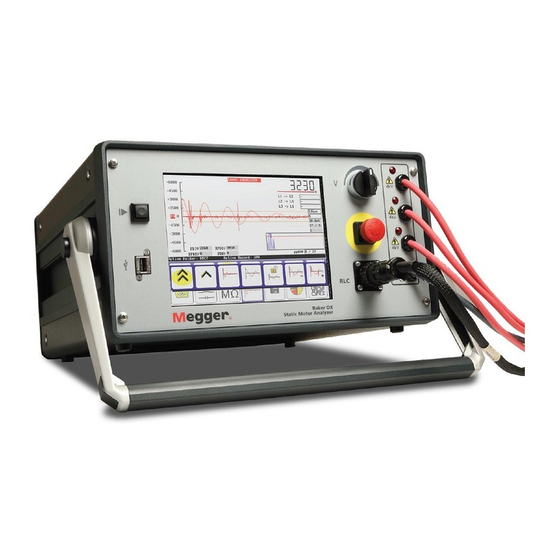
Page 6: Baker Dx Instrument Overview
Instrument Descriptions 1. Baker DX instrument overview Front panel controls Figure 1. Front panel controls Rear panel controls Figure 2. Rear panel controls www.megger.com... -
Page 7: User Interface Main Elements
Mode Submenu itself or popup menus that appear in the Display Area. Mode Menu—used to select the main mode of operation. Test and function modes are described below. The Mode Menu does not change, and is always available. Baker DX Series Static Motor Analyzer www.megger.com... -
Page 8: Test And Function Modes
The control icons for each mode appear in the submenu just above the Mode Menu. The Mode Submenu icons correspond to the Mode Menu item selected. In the following example, we see the descriptions of the Mode Submenu icons that appear when the RLC Tests icon is touched. Figure 5. Mode submenu icons example. www.megger.com... -
Page 9: Popup Menus
Figure 6. Popup menu appearing when the RLC test selection icon is touched. The details of this popup menu are provided in the example below. Figure 7. Popup menu icon descriptions for test type selection. Baker DX Series Static Motor Analyzer www.megger.com... - Page 10 If the voltage changes (such as during ramp up) the counter starts over. The pulse count also appears in the test report. www.megger.com...
-
Page 11: Preparing For Testing
Figure 9. Selecting the active folder and record for saving test data. 3. Touch the record and folder you want to use for your testing. The selected location will appear in the Status Bar as Active Folder and Active Record. Baker DX Series Static Motor Analyzer www.megger.com... - Page 12 1. To view existing data, touch the Report icon in the mode menu. 2. When you touch a folder in the Folder list, such as the MEGGER folder in the following example, the folder will be highlighted and all associated records that are in that folder will appear in the Record list.
-
Page 13: Determining A Known-Good Coil To Use As A Reference
DA/PI testing, or frequency shift in one or more waveform values during surge testing. An erratic PP EAR will often result and the shift could even trip the EAR limits. Baker DX Series Static Motor Analyzer www.megger.com... -
Page 14: Basic Testing Procedures
Inductance measurements can also be compared to previous measure- ments or values specified by the original equipment manufacturers. Inductance testing also provides impedance values and angles. DX capacitance tests measure only capacitance and D/Q. No impedance values or phase angle val- ues are included. www.megger.com... - Page 15 6. The default temperature is 25° C; key in the actual winding temperature to use for compensation and touch Done. NOTE The default temperature to correct to is defined in the User Settings. Refer to the Baker DX User Manual for more information. Baker DX Series Static Motor Analyzer www.megger.com...
- Page 16 2. Touch the Frequency icon then touch the frequency value in the popup menu. 3. Push and release the Start (PTT) button to run the inductance test. The inductance test will be run for all three phases automatically. The “Leads Energized” message will again appear at the top of the display. www.megger.com...
- Page 17 Figure 14. Capacitance test lead connections. 4. Touch the RLC test selection icon then touch the Capacitance test icon in the popup menu. 5. Push and release the Start (PTT) button to run the capacitance test. Baker DX Series Static Motor Analyzer www.megger.com...
-
Page 18: Conducting Dc Tests
3. For this example, touch the Standalone Unit icon. 4. If you know the type of insulation used in your motor, you can specify that by touching the Insulation Type selection icon. Choices include Thermo Plastic or Thermo Setting. www.megger.com... - Page 19 PTT functions are locked. The submenu will look like the following example while the tests are running: Figure 18. Test submenu items with Locked PTT and MOhm/PI test selected (both identified by yellow highlights). Baker DX Series Static Motor Analyzer www.megger.com...
- Page 20 As each test progresses, the software displays the test results in the fields located just above the Status Bar. The IR results appear after 60 seconds, the DA results after 180 seconds, and the PI test after 600 seconds. www.megger.com...
- Page 21 The demonstrated DC tests were chained together in a recommended best practice approach, but you may separate and perform them individually or in other combinations as required or preferred. Figure 21. DC Tests results screen from Reports. Baker DX Series Static Motor Analyzer www.megger.com...
-
Page 22: Conducting Surge Tests
4. As noted earlier, the operating voltage is the basis for the test voltage used during Surge testing. For this example, we continue to use the 480-volt motor with a maximum testing voltage of 2000 volts. 5. Press and hold the Start (PTT) button. The following popup menu appears. www.megger.com... - Page 23 10. The results of the winding tests of a wye or delta configuration will appear, as shown below. Save your results at this time. Performing subsequent surge tests will overwrite the displayed results. Figure 25. Surge test results screen. Baker DX Series Static Motor Analyzer www.megger.com...
- Page 24 PD events. The ramping up process is used to collect partial discharge inception voltage (PDIV) and RPDIV (R = repeated) data. 7. Increase the voltage to the target test voltage only. Partial discharge may or may not occur. www.megger.com...
- Page 25 Control knob to ramp down the voltage slowly and evenly. 9. Touch the Slow Ramp Rate icon to ramp down at the slower rate if not already selected. We recommend using the slow ramp rate for PD testing. Baker DX Series Static Motor Analyzer www.megger.com...
- Page 26 11. Touch the Lead 2 icon and repeat the process for the second phase then Lead 3 in turn. 12. Testing the second and third phases is identical to testing the first phase. After you complete phase 3 testing, save your results. www.megger.com...
- Page 27 Figure 29. PD three-phase report. PD data overlaid on surge waveform. The values for PDIV, RPDIV, RPDEV, and PDEV are indicated for each phase in the table at the top center portion of the display. Baker DX Series Static Motor Analyzer www.megger.com...
- Page 28 The left axis shows the voltage of the surge pulse. The waveforms are indicated by solid colored lines for each phase. The right axis shows the number of PD events recorded for each pulse. In this view, you can see how the PD activity rises and falls with the surge voltage. www.megger.com...
Need help?
Do you have a question about the Baker DX Series and is the answer not in the manual?
Questions and answers