Table of Contents
Advertisement
Quick Links
Advertisement
Table of Contents

Related Manuals for Megger Baker DX


Summary of Contents for Megger Baker DX
- Page 3 Service department: (970) 282-1200 or toll free at (800) 752-8272. Web: https://us.megger.com/ Information furnished in this manual by Megger Limited, is believed to be accurate and reliable. However, Megger Limited assumes no responsibility for the use of such information, for damages consequent to the use of this product, or for any patent infringements or other rights of third parties that may result from its use.
- Page 4 Megger Acquisition of Baker Instruments Megger Group Limited, a manufacturer of electronic test equipment and measuring instruments for power applications, acquired the Baker Instruments business from SKF Group in August of 2018.
- Page 5 Notices Declaration of Conformity Manufacturer’s Name and Address: Megger Baker Instruments 4812 McMurry Ave. Suite 100 Fort Collins, CO 80525 Equipment Description: Testers for Surge, DC Hi-Pot, and Winding Impedance of motors. Equipment Model Designations: DX Application of Council Directive 72/23/EEC on the harmonization of the laws related to Member...
- Page 6 Any unauthorized prior repair or adjustment will automatically invalidate the warranty. Megger warrants this instrument to be free from defects in materials and workmanship, where the equipment is used for its proper purpose. The warranty is limited to making good this instrument (which shall be returned intact, shipping paid, and on examination shall disclose to their satisfaction to have been defective as claimed).
- Page 7 4 — Using Baker DX Non-Test Functions Data Management Operations Managing Report Printing Operations Using System Settings 5 — Setting up the Baker DX Tester Positioning the Baker DX Safety Precautions for Baker DX Setup Baker DX Setup Procedures 6 — Setting up the Baker ZTX 7 —...
- Page 8 Low-impedance Armature and Coil Testing Using the Baker ZTX Troubleshooting Self-help and Diagnostics Applications: What to do First Service: What to do First Warranty Return Technical Specifications, Calibration, and Applicable Standards Calibration Information Applicable Standards Baker DX 71-030 User Guide EN V10 www.megger.com...
- Page 9 Table of Contents DC and Surge Tests Voltages Recommended Test Voltages RIC Templates Index megger.com...
- Page 10 Table of Contents viii Baker DX 71-030 User Guide EN V10 www.megger.com...
- Page 11 Located beside each red test lead on front panel of instrument and on back of unit. Labels on Equipment The following Danger notice label appears on the top of the DX unit itself. Figure 1. High voltage warning label. megger.com...
- Page 12 Safety Precautions Read and follow all safety precautions and safe operating practices in your manual. Do not exceed maximum operating capabilities of the Baker DX tester, power packs, or the Baker ZTX accessory. The general safety information presented here is for both operating and service personnel. You will find specific warnings and cautions throughout this manual where they apply.
- Page 13 NOTICE: The ground-fault system on the Baker DX will render it inoperative without a proper ground. When the host Baker DX tester is connected to a power pack, an inoperable condition will also affect the power pack.
- Page 14 Equipment Stop Button The Baker DX tester is equipped with a red Equipment Stop (E-Stop) button on the front panel of the unit. Use it to quickly discontinue a test and to shut off power to the power pack’s high- voltage circuitry.
- Page 15 Figure 3. Baker ZTX unit and Remote E-Stop Equipment Stop buttons. After being pressed, the button will remain locked in position until manually retracted by rotating the Equipment Stop button clockwise. A warning message will appear on the DX screen. megger.com...
- Page 16 This unit is for use at a maximum relative humidity of 80% for temperatures up to 31 °C (88 °F), decreasing linearly to 50% relative humidity at 40° C (104° F). This unit is intended for Installation Category II in a Pollution Degree II environment. Baker DX 71-030 User Guide EN V10 www.megger.com...
- Page 17 Baker DX testers are compatible with the Baker PP30, Baker PP40, and Baker PP85 power pack systems for very high-voltage testing, and with the Baker ZTX for armature testing. The DX family is also compatible with external safety lights and Equipment stop boxes.
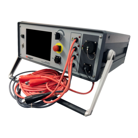
- Page 18 Baker DX Instrument Overview Front Panel Controls All Baker DX Series testers feature a large, 8-inch touch screen with a graphical user interface. The interface features a logical layout of large touch icons that improve ease of use, even with electrical gloves.
- Page 19 Three high-voltage test leads (red) and a ground lead (black) are provided for motor test connections The Baker DX uses high-voltage test leads for surge, Baker ZTX, and DC testing. Keep the leads clean and dry for best measurement performance.
- Page 20 5. Power Pack interconnect receptacle Configuration Options The Baker DX series includes seven models: DX4 (4 kV), DX6 (6 kV), DX6HO (6 kV), DX12 (12 kV), DX12HO (12 kV), the DX15 (15 kV), and the DX15A (15 kV with built-in ZTX). They have common base functions, but vary by capacity.
- Page 21 ATF-5000 armature test fixture. The maximum armature test voltage is 1500V. The Baker DX-15A model has all the features of the Baker DX-15 with the additional option of a built-in ZTX. Figure 7. Baker DX-15A; built-in ZTX functionality.
- Page 22 40,000 volts (Baker PP30 x85: 30,000V; Baker PP40: 40,000V). These units perform Surge and DC/HiPot tests when used with the Baker DX tester as the control and display. They incorporate a supply monitor for safe operation from a well-grounded supply.
- Page 23 The Baker ZTX is a high-current Surge test adaptor for DC motors, form coils, and other low- impedance windings. The following graphics show the Baker DX with the Baker ZTX unit along with several other options that can be used with the Baker DX unit.
- Page 24 Baker DX Instrument Overview Accessories Footswitch You can connect the footswitch (optional) to the Baker DX host or auxiliary units; it overrides the Start (PTT) button. The footswitch enables hands-free use of the unit and gives you additional operating position options.
- Page 25 Baker DX Instrument Overview Carrying Cases Optional carrying cases provide durable protection for the Baker DX. The Pelican case (shown below) protects sensitive equipment with a fully foam-lined, hard shell. This case has an extendable handle and wheels for easy transport.
- Page 26 Baker DX Instrument Overview Test Accessories The Baker DX also features accessories that facilitate testing including the ATP02-C test clips and the ATP02-P test probes. Clips are used during single-coil testing while the probes are used during armature bar-to-bar and span testing.
- Page 27 Surveyor DX is a complementing desktop computer software application that provides added value to Baker DX users by uploading Baker DX test data stored on a USB drive for archiving and reporting purposes. Uploaded data is saved in a database on the desktop computer.
- Page 28 Baker DX Instrument Overview Baker DX 71-030 User Guide EN V10 www.megger.com...
- Page 29 3 — Baker DX User Interface Overview The touch screen interface of the Baker DX family provides a logical, easy-to-navigate layout to conduct all tests with minimal user interaction. A light touch on the screen is all that is required to select an item.
- Page 30 The Waveform Selection icon is used to select optional coil test displays. The ZS Override (Zero Start Override) icon is used to tell the tester to go immediately to the Baker DX 71-030 User Guide EN V10 www.megger.com...
- Page 31 Baker DX User Interface Overview reference level, removing the need to ramp up and allowing the tester to reach the target voltage faster. Figure 20. Single-coil testing submenu example. In this example, the Surge test three-phase coil mode submenu is shown.
- Page 32 (removing the need to ramp up), allowing the tester to reach the target voltage faster. Other submenus for each mode—along with their descriptions—are provided throughout the manual in context for the applications described. Baker DX 71-030 User Guide EN V10 www.megger.com...
- Page 33 Baker DX User Interface Overview Popup Menus Popup menus appear when specific functions are selected during the testing process. In the example below, a popup appears in the Display Area when the RLC test selection icon (first icon from the left in the Mode Submenu) is touched.
- Page 34 The graphic above shows that the measurements being made are hot, ground, and open—the typical standard measurement configuration. In others, the connection and measurements will be hot-ground-ground, and the graphic will reflect that measurement type. Baker DX 71-030 User Guide EN V10 www.megger.com...
- Page 35 Baker DX User Interface Overview The following example shows controls that allow you to dynamically move through the tests being conducted. At the top of the Display Area, a set of display control buttons are used to facilitate movement from test measurement to test measurement; in this example, the buttons move you from coil to coil, and the X axis shows which coil measurement you are currently viewing.
- Page 36 NOTE: Touching the numbers shown at the top of the screen changes the units displayed for the results presented. However, touching other areas of the Main Display Area will stop the test and will result in an operator aborted test. Baker DX 71-030 User Guide EN V10 www.megger.com...
- Page 37 Baker DX User Interface Overview In surge mode, the elements change based on the type of coil selected for testing. In each mode, a pulse counter shows you the number of pulses applied at a specific voltage during the test. If the voltage changes (such as during ramp up) the counter starts over.
- Page 38 Baker DX User Interface Overview Baker DX 71-030 User Guide EN V10 www.megger.com...
- Page 39 4 — Using Baker DX Non-Test Functions Data Management Operations Managing Data Folders Moving from left to right on the mode menu, the first mode is activated by pressing the Data Folders icon. Touching this icon brings the Folder and Record lists into the Display Area as shown below.
- Page 40 Using Baker DX Non-Test Functions Creating New Folder and Records 1. The Baker DX stores test information using a system of folders and records. To create new folders, and then the records (test results) that are stored in the folders, touch the Data Folders icon.
- Page 41 Using Baker DX Non-Test Functions Current test results are saved in the highlighted folders and records. The active folders and records also appear in the Status Bar as shown in the example below. Figure 33. Active Folder and Active Record display example.
- Page 42 1. To view existing data, touch the Data Folder icon in the mode menu. 2. When you touch a folder in the Folder list, such as the Megger folder in the following example, the folder will be highlighted and all associated records that are in that folder will appear in the Record list.
- Page 43 Using Baker DX Non-Test Functions 4. When you touch the Display icon (functions like a print preview), submenu items appear that allow results shown in the Display Area to be viewed according to test type, or to be printed. Figure 35. Display submenu icons.
- Page 44 Test results from the most recent test are protected by a prompt to save the test data, including any time a completed test is abandoned to run another test. NOTICE: If you power off the unit before saving data, any unsaved test results will be permanently lost. Baker DX 71-030 User Guide EN V10 www.megger.com...
- Page 45 Inserting a Logo in Reports The Baker DX can store a logo for printing on test reports. To include a logo in a report, you will check the Include Logo box in the report header form described below.
- Page 46 Copy or move the image file to the USB drive, then remove the drive and insert it into the USB port on the front panel of the Baker DX. Go to the Reports screen and wait for the transfer to complete.
- Page 47 Using Baker DX Non-Test Functions Defining Report Header Information 1. To define the information that will appear in the header of your reports, touch the Report icon then the Report Header icon when the Reports submenu changes as shown below.
- Page 48 5. Touch Done on the submenu bar when you complete the form. NOTE: When moving to different records or folders, be sure to touch the Clear All button to ensure the report header field is not populated with old or inaccurate information. Baker DX 71-030 User Guide EN V10 www.megger.com...
- Page 49 3. Connect a USB printer to the USB port (installation of a printer driver is not necessary). When the printer is powered on and ready, touch the Print button. 4. The report will print with a logo (if used; Megger in this example) just to the left of the company name as illustrated below.
- Page 50 2. Wait for the file to save then touch OK. 3. When you finish collecting desired screen shots, remove the USB drive and insert it into a computer. 4. Acquire the DX Viewer utility software from the Baker DX product documentation CD or the Megger website (https://us.megger.com/static-electric-motor-analyzer-baker-dx- 1#software and install it on your computer where you can easily access it.
- Page 51 NOTICE: The System Settings functions are reserved for personnel with Maintenance Mode access and privileges; basic operators will not have access to this area. The Tester Config and Tester Debug icons are for use by Megger personnel only and provide access for hardware configuration functions used only during product assembly and updating.
- Page 52 Figure 45. Maintenance Mode popup menu. NOTE: This area can also be used to enter system settings in admin mode, but that mode is reserved for Megger personnel. The admin password is based on hardware specific to the machine and cannot be changed.
- Page 53 NOTICE: To avoid creating problems with the tester, Micro Step Settings should not be changed without first consulting Megger support. These fields are usually locked out. Use this screen to adjust the Voltage Ramp Rate, Temperature Scale (Celsius vs. Fahrenheit), DC Test Times (in seconds), and Surge Limits (Pulse-to-Pulse EAR and Line-to-Line EAR maximum limits in percent).
- Page 54 Figure 47. Multi-level Popup Menu example. Partial discharge testing uses settings in both the Voltage Ramp Rate and PD settings sections. Application of these parameters for PD testing is explained in more detail on the next page. Baker DX 71-030 User Guide EN V10 www.megger.com...
- Page 55 These levels are set in the User Settings screen under the PD settings heading on the lower left portion of the screen. NOTE: For more information on partial discharge testing, refer to the Megger Motor Testing Theory Reference Manual. Figure 48. PD settings in User Settings screen.
- Page 56 From the User Settings screen, select a fast ramp rate of no more than 50 volts and a slow ramp rate of no more than 10 volts to increase repeatability of RPDIV and RPDEV measurements. Figure 49. Setting ramp rates for PD testing. Baker DX 71-030 User Guide EN V10 www.megger.com...
- Page 57 Avoid placing the unit on other items other than power packs or flat surfaces. To prevent shock hazard, do not expose the Baker DX to rain, snow, or moisture. Avoid locations with high levels of dirt or dust. Baker DX Setup Procedures 1.
- Page 58 Setting up the Baker DX Tester Baker DX 71-030 User Guide EN V10 www.megger.com...
- Page 59 NOTICE: Review all safety information provided with the equipment and presented in chapter 1 —“General Operating Information” before setting up or operating the Baker ZTX. NOTE: The Baker DX includes an open ground detect feature. If an open ground is detected, a banner appears in the Display Area.
- Page 60 Setting up the Baker ZTX 4. Connect the high-voltage test leads of the Baker DX to the Baker ZTX unit’s recessed bars on the rear of the unit as labeled: Test lead 1 to the bar labeled “Test Lead 1.”...
- Page 61 High-voltage power pack leads. Leads 1 and 2 only for three-phase leads. Power Pack Low-impedance armature testing. ATF-5000 fixture or (PP85 only) or ATP02-P probes. AT101-ZTX Power Pack Low-impedance single-coil testing. ATP02-P probes or ATP02-C clips. (PP85 only) or AT101-ZTX megger.com...
- Page 62 5, creating a span of 5 bars. Bar 1 and 5 are contacted first, followed by bars 2 and 6, and so on until all bar spans are tested. Figure 54. ATF-4000 armature span test fixture. Baker DX 71-030 User Guide EN V10 www.megger.com...
- Page 63 3. Center the ground brushes on the selected bars by adjusting the ground arms then lock the arms in place with the Ground arm locking knobs. Figure 55. Positioning the surge test accessory on the armature. megger.com...
- Page 64 Setting up Fixtures, Test Accessories, and Lead Connections 4. Ensure the test lead cable is properly connected to the armature test fixture. Figure 56. Baker ZTX connected to bar-to-bar armature surge test accessory. Baker DX 71-030 User Guide EN V10 www.megger.com...
- Page 65 ATP02-C test clips. The clips’ connectors attach to source and sense connectors of the Baker ZTX, Baker PP85, or Baker DX15A. The test clips are attached directly to the coils being tested. Figure 57. ATP-02-C test clips. Figure 58. ATP02-C test clips connected to a single coil. megger.com...
- Page 66 The armature test low-impedance test probes can be used for bar-to-bar testing, though they are more commonly used in span testing. Figure 59. ATP-02-P test probes. Figure 60. ATP02-P armature test probes. NOTE: The ATP02-P test probes are used only for low-impedance testing. Baker DX 71-030 User Guide EN V10 www.megger.com...
- Page 67 For low-voltage single-coil testing, the tester’s low-voltage RLC test leads are used (leads 1 and 2 only). 1. Connect the low-voltage cables to a coil under test and proceed. 2. Ensure cables do not touch each other or a ground source during testing. Figure 62. Connecting low-voltage cables to a coil. megger.com...
- Page 68 3. Connect the ground cable to motor ground. 4. Ensure test/motor leads do not contact each other or the motor chassis during testing. Figure 63. Connecting high-voltage test leads to motor leads. Baker DX 71-030 User Guide EN V10 www.megger.com...
- Page 69 3. Connect the ground cable to motor ground. 4. Ensure test/motor leads do not contact each other or the motor chassis during testing. 5. Keep high-voltage test leads away from motor and RLC leads during testing. Figure 64. Connect RLC test leads to motor leads. megger.com...
- Page 70 2. Larger versions of the template are available in the appendix. 3. Connect the RLC test leads to the motor under test as described earlier. Figure 65. RIC test motor template. Baker DX 71-030 User Guide EN V10 www.megger.com...
- Page 71 NOTICE: Review all safety information provided with the equipment and presented in chapter 1 —“General Operating Information” before setting up or operating. Confirm that the Baker DX setup procedure has been followed. Refer to chapter 5 —“Setting up the Baker DX Tester” as needed.
- Page 72 6. Select test frequency. 7. Touch and release PTT. 8. Configure low-voltage test leads for capacitance testing. 9. Select Capacitance mode. 10. Touch and release PTT. 11. Save results. 12. Disconnect low-voltage test leads. Baker DX 71-030 User Guide EN V10 www.megger.com...
- Page 73 (Copper icon shown above). NOTE: In the test start screen as shown above, the value that first appears in the Temp (degC) field is originally defined in the system settings. If needed, you can change this value in the next step. megger.com...
- Page 74 NOTE: If you require another resistance test, running this test again will overwrite the current results unless you save it. Baker DX 71-030 User Guide EN V10 www.megger.com...
- Page 75 Inductance, Impedance, Phase Angle, and D/Q Tests Procedures This procedure starts where the resistance test was completed. With coil inductance tests, the Baker DX looks for imbalances and variations between the coil phases. The DX performs these tests at a single specified frequency.
- Page 76 Figure 70. Inductance test results screen. NOTE: Be sure to save the tests you want to report. If you require another inductance test, running this test again will overwrite the current results unless you save it. Baker DX 71-030 User Guide EN V10 www.megger.com...
- Page 77 Modify connections of the RLC test leads to a capacitor test configuration. 1. Connect RLC test lead 1 to any motor lead. 2. Connect RLC test lead 2 to ground. 3. Disconnect RLC test lead 3 and leave disconnected. Figure 71. Capacitance test lead connections. megger.com...
- Page 78 6. The submenu changes as shown in the example above with the 4 kHz frequency icon shown to identify the frequency at which the capacitance tests are conducted. (Capacitance tests are restricted to 4 kHz.). Baker DX 71-030 User Guide EN V10 www.megger.com...
- Page 79 (data will save to the selected folder). In any case, be sure to save your data before going on to the next set of tests. The next test will overwrite unsaved test data. 9. Disconnect the low-voltage resistance test leads and set them safely aside. megger.com...
- Page 80 NOTICE: Review all safety information provided with the equipment and presented in chapter 1 —“General Operating Information” before setting up or operating. Confirm that the Baker DX setup procedure has been followed. Refer to chapter 5 —“Setting up the Baker DX Tester” as needed.
- Page 81 NOTE: No further testing is worthwhile until you find the reason for low MegOhm readings and make any necessary corrections. For more details, refer to Megger Motor Testing Theory Reference Manual, which has supporting information and details about DC testing capabilities and methods.
- Page 82 Icons for installed options will appear in a popup menu, presenting a choice of operation as a standalone unit or power pack unit. Figure 75. Configuration Options popup menu. 4. For the following example, touch the Standalone Unit icon. Baker DX 71-030 User Guide EN V10 www.megger.com...
- Page 83 1,960 – 480 = 1,480. Using three increments for this example, (1,500 / 3 = 500 v), each increment for the step DC HiPot would be 500 volts (500 v, 1000 v, and 1500 v). To run a final DC-HiPot, set the voltage at 2000 v. megger.com...
- Page 84 500 volts and use the Fast or Slow Ramp Rate controls as needed to quickly fine tune the level. Figure 79. Ramp Rate controls. Touch the MOhm/PI icon to start the MegOhm insulation resistance (IR), dielectric analysis (DA), and polarization index (PI) tests. Baker DX 71-030 User Guide EN V10 www.megger.com...
- Page 85 HIPOT TRIP message, and readies the tester for a new test. 7. Touch the Save icon to save the test results to the active folder and active record. Conduct a Conventional DC HiPot Test Alternatively, you can conduct just a conventional DC HiPot test to complete your DC testing. megger.com...
- Page 86 Each of these demonstrated DC tests were chained together in a recommended best-practice approach, but you may separate and perform them individually or in other combinations as required or preferred. Figure 82. DC Tests results screen. Baker DX 71-030 User Guide EN V10 www.megger.com...
- Page 87 NOTICE: Review all safety information provided with the equipment and presented in chapter 1 —“General Operating Information” before setting up or operating. Confirm that the Baker DX setup procedure has been followed. Refer to chapter 5 —“Setting up the Baker DX Tester” as needed.
- Page 88 4. Touching the Configuration Options icon shows you the options that are installed such as operation as a standalone unit, with a power pack, with a Baker ZTX, or with a power pack containing a built-in ZTX. Figure 84. Configuration options popup menu. Baker DX 71-030 User Guide EN V10 www.megger.com...
- Page 89 11. Alternately use the Fast/Slow Ramp Rate icons to control the rate of voltage change while rotating the Voltage Output Control knob. Raise the voltage to the desired level for the motor under test (1960 volts for this example). megger.com...
- Page 90 17. If needed, you can also clear all test results by touching the Clear Data icon then start the process over. NOTICE: Selecting the Clear Data icon immediately and permanently deletes all data and the reference test. Baker DX 71-030 User Guide EN V10 www.megger.com...
- Page 91 Procedures for Testing with the DX Host Partial Discharge Testing Overview and Preparation Surge testing with the Baker DX includes the optional feature of partial discharge (PD) testing, which involves detecting localized, partial bridging between conductors due to dielectric breakdown caused by high-voltage stress that does not fully short the two conductors. These discharges, when severe enough, can create a persistent visible glow known as corona.
- Page 92 DC testing. PD testing does not use the DX features for DC testing compensation and recording. For PD testing, recording ambient temperature and humidity is a manual process. Baker DX 71-030 User Guide EN V10 www.megger.com...
- Page 93 PD threshold (mV) value. Figure 90. User Settings screen, PD value settings menus. 5. Return to the surge screen. 6. Again, apply just the initial surge voltage to the device (do not ramp up). megger.com...
- Page 94 10. If needed, re-adjust the PD threshold (mV) so that it is above the detected noise floor so that only PD will trip the event indicator. The DSS value must always be lower than the PD threshold value. Baker DX 71-030 User Guide EN V10 www.megger.com...
- Page 95 5. Hold down the PTT button and use the Voltage Output Control knob to ramp up the voltage slowly and evenly. 6. Touch the Fast Ramp Rate icon to ramp at the higher rate if desired, but ensure that ramping is slow enough to allow observation of PD events as described above. megger.com...
- Page 96 7. To acquire the extinction voltages, hold down the PTT button and use the Voltage Output Control knob to ramp down the voltage slowly and evenly. 8. Touch the Slow Ramp Rate icon to ramp down at a slower rate if desired. Baker DX 71-030 User Guide EN V10 www.megger.com...
- Page 97 PD activity in each phase, a short process is added to the end of testing each phase. The Baker DX reporting function stores the last waveform captured during testing. To capture a screen shot for each test phase that displays PD activity, ramp voltages back up to at least the PDIV level for each phase after acquiring the extinction voltages.
- Page 98 Procedures for Testing with the DX Host Options for Displaying PD Data During Testing The Baker DX is equipped with multiple viewing options for observing the partial discharge activity on the unit being tested. The data gathered for PD detection is separate from the data gathered for the surge waveform, allowing you to manipulate the PD waveform independently of the surge waveform if desired.
- Page 99 Figure 97. PDIV and RPDIV displayed in locked view. In the following example, the waveforms are locked and the PD waveform signal expands with the surge waveform, down to 2µs per division—the maximum surge zoom level of the Baker DX tester.
- Page 100 When the two waveforms are not synchronized, the activity areas on the PD waveform will not correspond with their overlaid locations on the surge waveform. This view provides maximum resolution for the sampling frequency of the partial discharge detector. Figure 99. Voltages shown in expanded unlocked view. Baker DX 71-030 User Guide EN V10 www.megger.com...
- Page 101 Surge test. Figure 100. PD three-phase report. PD data overlaid on surge waveform. The values for PDIV, RPDIV, RPDEV, and PDEV are indicated for each phase in the table at the top center portion of the display. megger.com...
- Page 102 The right axis shows the number of PD events recorded for each pulse. In this view, you can see how the PD activity rises and falls with the surge voltage. Baker DX 71-030 User Guide EN V10 www.megger.com...
- Page 103 Set Reference icon. 8. After you have established the reference, you will want to set up the tester to make it easier to test subsequent coils. megger.com...
- Page 104 3. Ensure that the zero-start override is set. 4. You can now test a group of “identical” coils by sequentially connecting the test leads to each coil, pushing the Start button and holding it for approximately 10 pulses. Baker DX 71-030 User Guide EN V10 www.megger.com...
- Page 105 3. Touch Yes when the following message appears: Figure 106. Override zero-start functionality message dialog. 4. After you set the ZS Override level, the Voltage Output Control knob on the unit will no longer control the unit’s output voltage. megger.com...
- Page 106 The Baker DX allows you to export and import reference waveforms. The feature is useful for retaining known good reference waveforms if the tester’s data storage must be reformatted. NOTE: Due to slight variations in the capacitance of each Baker DX tester, you should not move or share reference waveforms among multiple testers.
- Page 107 NOTE: If multiple reference waveforms were saved in the same USB file during the reference waveform export, all the reference waveforms in that USB file will be imported to the selected folder on the Baker DX. Each reference waveform retains its name so it can be selected during coil testing.
- Page 108 Figure 108. Testing single coils with the Baker DX—three-lead testers. NOTE: For Baker DX testers using the single-lead option, connect the red test lead to coil lead 1 and the black ground lead to coil lead 2.
- Page 109 3. Touch the Coil mode selection icon to bring up the popup menu shown below. Figure 110. Coil mode selection popup menu. 4. Select the Single-coil mode icon for this example. (Other uses of this process would select other options such as Arm Span, Arm Bar, or DC IP). megger.com...
- Page 110 Figure 112. Coil test results screen; reference and last waveform displayed. 10. When you have completed testing all your coils, touch the Save icon to save the test results in the active folder and record. Baker DX 71-030 User Guide EN V10 www.megger.com...
- Page 111 Switching Active Leads By default, the Baker DX tests coils with lead 1 set as the active lead (hot side). Surge flow starts from this direction. If you want to switch surge flow direction to test your coils, you should consider the following issues.
- Page 112 You should also notice that the Y-axis on the Active EAR Bar Graph has a -1 value at its bottom. This is so the EAR zero line can be displayed in the graph. Baker DX 71-030 User Guide EN V10 www.megger.com...
- Page 113 You will then see another dialog asking: “Also Clear Reference Waveform?” Touch No to keep the reference. If you touch Yes to clear the reference, you will need to set a new reference to continue testing and/or to use in future testing. megger.com...
- Page 114 6. Hold down the PTT button and use the Voltage Output Control knob to ramp up the voltage slowly and evenly. 7. Ensure that ramping is slow enough to allow observation of PD events. Baker DX 71-030 User Guide EN V10 www.megger.com...
- Page 115 8. To acquire the extinction voltages, hold down the PTT button and use the Voltage Output Control knob to ramp down the voltage slowly and evenly. 9. Touch the Slow Ramp Rate icon to ramp down at a slower rate if desired. megger.com...
- Page 116 Reference icon and then touch the ZS Override icon. NOTE: Refer to “Determining a Known-good Coil to Use as a Reference” earlier in this chapter for more information on identifying a known good coil and using the reference features. Baker DX 71-030 User Guide EN V10 www.megger.com...
- Page 117 Figure 119. Override zero start message dialog. 3. Test each subsequent coil by connecting the clips to each coil and pressing and holding the Start button on the DX Host (or footswitch) for approximately 10 pulses. Figure 120. PD ZSO, no PD events indicated. megger.com...
- Page 118 Figure 121. Coil EAR report example. This report shows the bar graph for each coil, but not the EAR waveforms themselves. The waveforms are saved, but are only available when using the Surveyor DX software. Baker DX 71-030 User Guide EN V10 www.megger.com...
- Page 119 During testing, the software generates multiple surge pulses over the course of a test cycle. Within each surge pulse, the tester collects the number of PD events detected. The report includes the minimum, average, and maximum number of PD events detected for each coil displaying PD activity. megger.com...
- Page 120 Such behavior typically indicates that your PD threshold is set too low or the PD # events level is set too low. Baker DX 71-030 User Guide EN V10 www.megger.com...
- Page 121 NOTICE: Review all safety information provided with the equipment and presented in chapter 1 —“General Operating Information” before setting up or operating. Confirm that the Baker DX setup procedure has been followed. Refer to chapter 5 —“Setting up the Baker DX Tester” as needed.
- Page 122 Procedures for Testing with the DX Host Span Test Procedures The Baker DX as a standalone unit can perform DC FC (field coil) and span (armature winding, or arm span) testing. The armature span test is typically used as a substitute when the low- impedance functionality of a Baker ZTX tester or accessory is not available (includes Baker AT-101 ZTX, Baker PP85 power pack, or Baker DX-15A).
- Page 123 Releasing the PTT, footswitch, or fixture button too soon can result in a collapsed waveform and errant test data being collected. 10. When you have completed testing all bars of the armature, return the Voltage Output Control knob to Min (full counterclockwise rotation). megger.com...
- Page 124 After saving, the data can be recalled for analysis, printed using a printer connected to the DX USB port, or saved to a USB drive for uploading to a computer using the Surveyor DX software. Baker DX 71-030 User Guide EN V10 www.megger.com...
- Page 125 The fourth icon—Single Coil in this case—shows the type of coil being tested. That selection can also be changed by touching the icon. This icon is a notation in the result that also appears in the report when printed. megger.com...
- Page 126 Mode Menu then selecting the Armature Coil Mode icon in the Mode Submenu. 5. Select the coil or winding type to test as shown in the example below. Figure 130. Selecting coil type to test—single coil selected. Baker DX 71-030 User Guide EN V10 www.megger.com...
- Page 127 7. Move the probes (or leads 1 and 2) to the next set of armature bars or to the next coil then push and release the Start (PTT) button. Repeat the process until all coils/windings have been tested. 8. Touch the Save icon to save your test results. megger.com...
- Page 128 The DX will plot the measurements over the rotation of the rotor, which helps identify rotor defects. Baker DX 71-030 User Guide EN V10 www.megger.com...
- Page 129 5. Starting at 0 degrees, push the Start (PTT) button to execute the first set of tests on that position of the rotor. The Baker DX will automatically run three inductance tests— one for each lead. The results of these tests are presented in the Display Area.
- Page 130 As you select different measurement sets using the control icons on the right edge of the screen (for AC resistance, inductance, phase angle, and impedance) the Y-axis changes accordingly to display the proper units for each measurement type and scale. Baker DX 71-030 User Guide EN V10 www.megger.com...
- Page 131 You can then go to other tests as needed and replace their results in the same manner, or you can touch the far-right display control to return to the next test position and continue your testing. megger.com...
- Page 132 120, 180, and 360 as needed (depending on the number of poles in the motor). 9. When you have completed your tests, touch the Save icon to store your test results. Baker DX 71-030 User Guide EN V10 www.megger.com...
- Page 133 The Baker AT-101 ZTX extends the capabilities of the Baker DX to enable low-impedance coil testing of the type found in DC armatures and other coils. The Baker DX as a standalone unit can perform DC FC (field coil) and span (armature coil, or arm span) testing. The arm span test is typically used as a substitute for not having the low-impedance capability of the Baker ZTX arm span test accessory.
- Page 134 8. From this point, the process is essentially the same as the standard process for Surge testing single coils. Refer to the “Surge testing procedure for single-coil mode” found earlier in this chapter for detailed instructions. Baker DX 71-030 User Guide EN V10 www.megger.com...
- Page 135 Arm data and it will appear on the results as such. Running the test continues adding armature coils up to 400, after which you must create a new record for an armature with more commutator bars. 11. Touch the Report icon then the Display icon to view the commutator bar results. megger.com...
- Page 136 Procedures for Testing with the Baker ZTX In the simple example below, you can see the test results for interpole coil #4. Figure 140. Low-impedance coil test results screen—using ZTX. Baker DX 71-030 User Guide EN V10 www.megger.com...
- Page 137 DX, please take the following steps before calling or returning the unit. By performing these procedures and having the requested information available will help Megger Service or Applications departments analyze the situation to provide you with an appropriate response.
- Page 138 If none of the descriptions fits your situation or they do not help you with your problem, ensure that you have basic information about the tester and specific information about the motor being tested available when calling or faxing Megger Baker Instruments. Example test and specific information include: HP rating ...
- Page 139 Alternatively, an isolation transformer (of appropriate VA rating) may be used between the generator and the Baker DX. An earth ground is made on the isolated secondary side of the isolation transformer, which is then available to properly ground work surfaces and test equipment—including the Baker DX.
- Page 140 Sometimes, issues arise that have simple solutions that you can resolve on your own, negating the need to return a unit may. Please perform the following checks to determine whether you have such an issue before returning the unit to Megger Baker Instruments. DC Test Display Checks If no voltage or current shows, one of three problems might exist: ...
- Page 141 Megger for warranty repair. You must fill out and return the Warranty Return Form on the following page with the tester to obtain warranty service. This form will help Megger identify the problem, quickly repair the unit, and return it. megger.com...
- Page 142 Include this form with the tester you are returning. Copy this form to send to Megger and make a copy for your records before sending. NOTE: Be sure to follow the guidelines for shipping when sending the tester to Megger Baker Instruments. Company Name: Your Name:...
- Page 143 Technical Specifications, Calibration, and Applicable Standards Table 3. Baker DX series specifications. Model-specific tests 4 and 6 kV 6 kV HO 12 kV 12 kV 15/15A models model model 15 kV model models DC tests Voltage accuracy: Maximum resistance: > 25/50 GΩ...
- Page 144 3% accuracy 2.6 to 26 μF at at 60 Hz: 4000 Hz: 0.01 to 0.15 Ω at 5% accuracy 3% accuracy 4000 Hz: 60 Hz: Phase accuracy at < 2 degrees 60 Hz: Baker DX 71-030 User Guide EN V10 www.megger.com...
- Page 145 Technical specifications, calibration, and applicable standards Calibration Information New Baker DX testers are calibrated at the manufacturing facility before shipping. Calibration is recommended annually to ensure continued optimum performance. For more information, please contact Megger Baker Instruments, Fort Collins, CO for current calibration information.
- Page 146 IEEE Customer Service 445 Hoes Lane Piscataway, NJ 08855-1331 Phone: 1-800-678-IEEE Fax: 908-981-9667 www.ieee.org Reprints of NEMA standards are available from: National Electrical Manufacturers Association (NEMA) Global Engineering Documents Phone: 1-800-854-7179 International: 303-379-2740 Baker DX 71-030 User Guide EN V10 www.megger.com...
- Page 147 DC and Surge Tests Voltages Recommended Test Voltages Megger Baker Instruments has a recommended standard (see table) for test voltages for DC tests and Surge tests conducted on a motor, generator, or transformer. That standard is twice the AC line voltage plus 1,000 volts.
- Page 148 Per Unit V Line × 4E + 5,000 0.2 us, 65% 6,920 4,498 7,300 4,745 7,400 4,810 2,300 1,878 14,200 9,230 4,160 3,397 21,640 14,066 6,900 5,634 32,600 21,190 13,800 11,268 60,200 39,130 Baker DX 71-030 User Guide EN V10 www.megger.com...
- Page 149 RIC Templates Figure 141. RIC template 1. megger.com...
- Page 150 RIC templates Figure 142. RIC template 2. Baker DX 71-030 User Guide EN V10 www.megger.com...
- Page 151 ATP02-C test clips 55 DC test procedures 72 ATP02-P test probes 56 DC tests using DX host 70 defining report header information 37 Baker DX-15/DX-15A 11 deleting a folder 34 BakerAT101-ZTX 13 deleting data 103 bar-to-bar armature test fixture 52...
- Page 152 Importing reference waveforms from an open ground detect external USB drive 97 setting 41 inductance test 65 options for displaying PD data during inductance test using DX host 61 testing 88 inserting logos in reports 35 Baker DX 71-030 User Guide EN V10 www.megger.com...
- Page 153 1 polarization index test 70 safety precautions 2, 47 popup menus 23 Selecting insulation type 73 positioning the Baker DX 47 power packs 12 selecting test voltage for span test 111 power requirements 6 self-help and diagnostics 127...
- Page 154 88 PD testing–three-phase mode 82 waveforms unlocked 88 temperature scale setting 43 ZTX armature testing 123 test accessories 16 ZTX emergency stop 5 test and function modes mode menu icon descriptions 20 Baker DX 71-030 User Guide EN V10 www.megger.com...
- Page 155 Index megger.com...
- Page 156 megger.com...
Need help?
Do you have a question about the Baker DX and is the answer not in the manual?
Questions and answers