Table of Contents
Advertisement
Quick Links
Megger Head Office
Megger Limited
Archcliffe Road
Dover
Kent
CT17 9EN
ENGLAND
T:
+44 (0)1 304 502101
F:
+44 (0)1 304 207342
Manufacturing Sites
Megger Limited
Archcliffe Road
Dover
Kent
T:
+44 (0)1 304 502101
F:
+44 (0)1 304 207342
Megger USA - Dallas
4271 Bronze Way
Dallas TX 75237-1019
USA
T:
+1 800 723 2861 (USA only)
T:
+1 214 333 3201
F:
+1 214 331 7399
E:
ussales@megger.com
This instrument is manufactured in the United States.
The company reserves the right to change the specification or design without prior notice.
Megger is a registered trademark.
Microsoft and Windows are either registered trademarks or trademarks of Microsoft Corporation in the United States
and/or other countries.
© Megger Limited 2018
Megger GmbH
Obere Zeil 2 61440
Oberursel,
GERMANY
T:
06171-92987-0
F:
06171-92987-19
Megger AB
Rinkebyvägen 19, Box 724,
SE-182 17
DANDERYD
T:
08 510 195 00
E:
seinfo@megger.com
Megger USA - Valley Forge
Valley Forge Corporate Center
2621 Van Buren Avenue
Norristown
Pennsylvania, 19403
USA
T:
1-610 676 8500
F:
1-610-676-8610
Megger Baker Instruments
4812 McMurry Avenue, Suite 100
Fort Collins, CO 80525
USA
T:
+1 970-282-1200
F:
+1 970-282-1010
E:
baker.sales@megger.com
E:
baker.tech-support@megger.com
www.megger.com
Advertisement
Table of Contents

Related Manuals for Megger Baker AWA-IV


Summary of Contents for Megger Baker AWA-IV
- Page 1 Kent CT17 9EN ENGLAND +44 (0)1 304 502101 +44 (0)1 304 207342 Manufacturing Sites Megger Limited Megger GmbH Megger USA - Valley Forge Archcliffe Road Obere Zeil 2 61440 Valley Forge Corporate Center Dover Oberursel, 2621 Van Buren Avenue Kent...
- Page 2 Baker AWA-IV Static Motor Analyzer Quick Reference Guide Part number: 71-050 EN V3...
- Page 3 Copyright Megger. All rights reserved. No part of this handbook may be copied by photographic or other means unless Megger have before-hand declared their consent in writing. The content of this handbook is subject to change without notice. Megger cannot be made liable for technical or printing errors or shortcomings of this handbook.
- Page 4 Failure to heedsafety precautions can result in injury or death from severe electrical shock. Additional information reference The Baker AWA-IV Quick Reference Guide is intended to introduce users to the analyzer and its basic operating procedures. For complete safety information anddetailed information on the device, end-user license agreement, and CE conformity refer to the Baker AWA-IV User Manual.
-
Page 5: Table Of Contents
Table Of Contents 1. INSTRUMENT DESCRIPTIONS....................Baker AWA-IV 2 kV/4 kV model front panel................Baker AWA-IV 6 kV/12 kV model front panel................2. PREPARING FOR TESTING....................Process overview........................Creating or opening a database....................Selecting a motor to test......................Creating a new Motor ID...................... -
Page 6: Instrument Descriptions
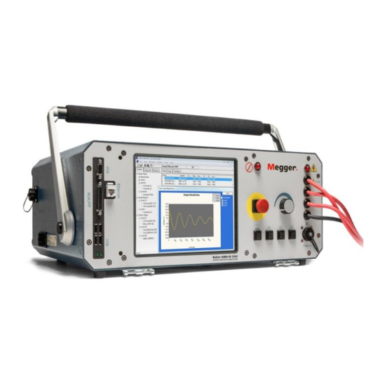
1. Instrument Descriptions Baker AWA-IV 2 kV/4 kV Model Front Panel All Baker AWA-IV series analyzers feature an eight-inch touch screen with a graphical user interface. The interface features a logical layout of touch icons that improve ease of use. - Page 7 AWA-IV 12kV analyzers have three red test leads for low-voltage resistance testing (no black lead). High-voltage test leads The Baker AWA-IV uses high-voltage test leads for surge, Baker ZTX, and DC testing. You must keep the leads clean and dry for best measurement performance.
-
Page 8: Baker Awa-Iv 6 Kv/12 Kv Model Front Panel
Instrument Descriptions BAKER AWA-IV 6 KV/12 KV MODEL FRONT PANEL Figure 3. Front panel controls for Baker AWA-IV 6 kV and 12 kV models. CAUTION It is important to note that test lead clips have exposed metal areas. Do not touch the clips while tests are running. Always exercise care to ensure the clips are not placed in proximity to the frame or ground potential. -
Page 9: Preparing For Testing
Each step is described in more detail in this chapter. CREATING OR OPENING A DATABASE 1. Start the Baker AWA-IV application by clicking on the icon on the tester screen or the MS Windows Start button. 2. Click on the appropriate radio button for creating a new database or opening an existing one. -
Page 10: Selecting A Motor To Test
Motor ID. To add a new Motor ID to the selected database, click on the Add button. 2. Click on the Clear button to remove all information currently entered in the fields. 3. Type the Motor ID, Location, Building, and name plate information in the appropriate fields. www.megger.com... - Page 11 8. The new motor will appear in the motor tree on the left side of screen. 9. You can then view the tests selected for the motor along with the test parameters then make adjustments if needed to better suit your testing objectives. Baker AWA -IV Static Motor Analyzer www.megger.com...
-
Page 12: Creating A New Test Id
Password field. To change a password, click on Change Password, type in the current password (if applicable), enter the new password and confirm then click on Set Password. 4. Click OK to close the password dialog box. Figure 7. Setting a password within the Tests tab. www.megger.com... - Page 13 8. You can further modify the Test ID by selecting the desired tests to be performed via the On/ Off buttons Figure 9. Selecting tests to perform, and controls for configuring or viewing test parameters. Baker AWA -IV Static Motor Analyzer www.megger.com...
- Page 14 Figure 10. Selecting test parameters from the DC Tests Setup screen. 10. Click Save to save the changes made to the new Test ID or click OK in response to a confirmation dialog appearing after making parameter changes. The new Test ID will be added to the list. www.megger.com...
-
Page 15: Selecting Tests And Setting Up Test Parameters
Figure 11. Selecting tests to perform, and controls for configuring or viewing test parameters. NOTE The following sections provide brief introductions to each test setup screen. For details on the screens and the parameters set within, refer to the AWA- IV user manual. Baker AWA -IV Static Motor Analyzer www.megger.com... - Page 16 4. The Test Results section shown at the bottom of the screen provides a view of the results collected when the test runs automatically or semiautomatically. You can also use this section directly during manual testing. 5. When you have completed your setup, close the screen. www.megger.com...
- Page 17 6. The “Run Tests” buttons near the bottom left of the screen are used to control testing during manual testing. The Voltage and Current displays to the right show you value being measured during testing. 7. When you have completed your setup, close the screen. Baker AWA -IV Static Motor Analyzer www.megger.com...
- Page 18 2. Set each value to a desired level and click Next. Figure 15. Step-Voltage Configuration Wizard; setting voltage parameters. 3. Add or delete steps within this screen as needed, then click Finish to save the setup. 4. When you have completed your setup, close the screen. www.megger.com...
- Page 19 When using ZS (Zero Start) Override, test voltage will not start at zero. Because the tester will immediately apply higher test voltages to the motor, take all precautions to avoid injury or death from severe electrical shock. Baker AWA -IV Static Motor Analyzer www.megger.com...
- Page 20 Some issues can be erroneous high resistance imbalance in coil testing due to increased inductance, inability to polarize for DA/PI testing,or frequency shift in one or more waveform values during surge testing. An erratic PP EAR will often result, and the shift could even trip the EAR limits. www.megger.com...
-
Page 21: Basic Testing Procedures
Motor ID that begins with those characters. „ Otherwise, scroll down the list until the Motor ID is located. Double click on the Motor ID or highlight the Motor ID and click the Display button to select. Baker AWA -IV Static Motor Analyzer www.megger.com... - Page 22 The Route Editor dialog box appears to help you add, rename, and delete routes. It also provides tools to add, remove, and change the order of the Motor IDs within a list. Figure 18. Use the Route Editor to manage route information. www.megger.com...
-
Page 23: Running Tests Automatically, Semi-Automatically, Or Manually
Resistance and surge tests even allow you to test individual leads. Tests can also be run manually using the analyzer’s front panel controls. Figure 20. Controls within setup screens to run tests manually. Baker AWA -IV Static Motor Analyzer www.megger.com... - Page 24 Figure 21. Safe to Turn On dialog box; message content can vary. Follow the instructions in the dialog to continue the testing process. When all tests have been run, the test data will automatically be saved to the database and the main test screen will reappear. www.megger.com...
-
Page 25: Test Sequence
Basic Testing Procedures NOTE Not all Baker AWA-IV testers have low-voltage test leads. If this option is not available, this screen will be slightly different; however, the test operation is the same. TEST SEQUENCE The following sequence of tests will run automatically. If a test fails, the software will stop the testing process, leads will be discharged and grounded, and you will be presented with choices for continuing testing if applicable. - Page 26 The PI test should not be used as the basis for any motor acceptance criteria. It should be used as a trending and diagnosis tool along with other test results, including the PI curve generated. If the Test ID was set up for a DA test, the test duration will be three minutes (180 seconds). www.megger.com...
- Page 27 During testing, the voltage will be slowly increased on lead 1 to the voltage specified in the Test ID. If no pulse-to-pulse EAR failures are detected, leads 2 and 3 will be tested. A shift to the left in the waveform patterns is a common indicator of weak insulation. Baker AWA -IV Static Motor Analyzer www.megger.com...
-
Page 28: Reviewing Test Results/Data
The Results Summary tab (accessed from the bottom of the pane) presents a Date/Time section at the top of the screen and a spreadsheet style view occupying the main display area. Figure 23. Data tab showing example results; Date/Time window. www.megger.com... - Page 29 For example, review the PI test by clicking on the PI tab. The PI view will display the PI/DA graph along with a table of the current and megohm readings gathered at specific times. The PI voltage, DA ratio, and PI ratio are displayed on the right side. Baker AWA -IV Static Motor Analyzer www.megger.com...
- Page 30 Basic Testing Procedures Figure 25. Example PI test results. The Surge test data can be reviewed by pressing the Surge tab Figure 26. Example Surge test results. www.megger.com...
-
Page 31: Printing Reports
NOTE For more detailed information on printing reports along with additional information on testing, results analysis, recommended test voltages, applicable standards, data transfer, and more refer to the Baker AWA IV User Manual. Baker AWA -IV Static Motor Analyzer www.megger.com... - Page 32 Notes Baker AWA -IV Static Motor Analyzer www.megger.com...
Need help?
Do you have a question about the Baker AWA-IV and is the answer not in the manual?
Questions and answers