
Related Manuals for Megger BD-59095


Summary of Contents for Megger BD-59095
- Page 1 99 Washington Street Melrose, MA 02176 Phone 781-665-1400 Toll Free 1-800-517-8431 MOM2 Visit us at www.TestEquipmentDepot.com MOM2 Win Micro-ohmmeter User’s Manual Art No. ZP-BD03E Doc. BD0333FE V06a 2016...
- Page 3 © 2013-2016, Megger Sweden AB. All rights reserved. The contents of this manual are the property of Megger Sweden AB. No part of this work may be reproduced or transmitted in any form or by any means, except as permitted in written license agreement with Megger Sweden AB. Megger Sweden AB has made every reasonable attempt to ensure the completeness and accuracy of this document.
-
Page 4: Table Of Contents
Contents 1 Safety To choose measurement time ......22 ..............6 To choose I > I min or I = I max ......22 Working at low temperatures ......23 1.1 Safety instructions ..........6 Kelvin Clamp/Probe practice ......23 1.2 Symbols on the instrument ......... - Page 5 Manual connecting .......... 35 7.5 Read the measurement log ....... 37 Export data to file ..........38 Delete all data on the instrument ..... 38 7.6 User settings ............. 39 Read existing settings ........39 Program "User" positions ........ 39 7.7 Calibration ............
-
Page 6: Safety
Never open a circuit breaker while MOM2 is yourself the warranty is no longer valid. Refer connected to it. all servicing to Megger authorized personnel. Connection points for current cables can be- If you need to return the instrument, please come hot during current generation. -
Page 7: Symbols On The Instrument
1 SAFETy 1.2 Symbols on the instrument Caution, refer to accompanying docu- ments. Protective conductor terminal. WEEE, Waste Electrical and Electronic Equipment. Please utilize your lo- cal WEEE collection facilities in the disposal of this product and otherwise observe all applicable requirements. Equipment complies with current EU directives. -
Page 8: Introduction
2 INTRODUCTION Introduction 2.1 Basic technical The MOM2 is designed to measure the resistance of circuit breaker contacts, bus-bar joints, contact ele- description ments in bus-bars and other high-current links. When contact resistance rises because of oxidation, The output current is delivered from a supercapacitor loosened or improperly tightened threaded joints, which is charged from the built-in rechargeable bat- temperatures rise abnormally at the points of contact. -
Page 9: Dualground - Both Sides Grounded
2 INTRODUCTION 2.2 DualGround – Both sides grounded With MOM2 it is possible to make measurements according to the DualGround™ method. The most im- portant advantage is improved safety but the method is also easier and saves time. The number of tasks is reduced when the ground cable does not need to be disconnected and reconnected. -
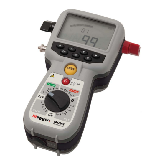
Page 10: Mom2 Overview
3 MOM2 OVERVIEW MOM2 overview 3.1 The instrument 10 11 Bottom view Top view MOM2 ZP-BD03E BD0333FE... - Page 11 3 MOM2 OVERVIEW Current output terminal (-) Function selector Current output terminal (+) 0.1 s Test positions Protective conductor terminal 0.6 s Measurement time with I > I min Display minimum current guaran- ▪ The display offers a combination of analogue arc and a dual digital readout: 0.1 s Test positions...
-
Page 12: Accessories
3 MOM2 OVERVIEW 3.2 Accessories 3.3 Optional accessories ▪ Test cables with Kelvin probes (one with trigger) Test cables with Kelvin probes (current & sense) 2 x 1.3 (4 ft) m (one with trig button) GA-90000 Test cables with Kelvin clamps Test cables with Kelvin clamps (current &... - Page 13 4 FUNCTIONS AND SET UP BD0333FE ZP-BD03E MOM2...
-
Page 14: Functions And Set Up
4 FUNCTIONS AND SET UP Functions and set up 4.1 General 4.2 Test positions I > I min Internal software version Minimum current is set in position SET / I min. When turning the function selector from OFF to any Generation / measurement time: 0.1 s, 0.6 s or 3 s. -
Page 15: Bluetooth
4 FUNCTIONS AND SET UP 4.3 Bluetooth – SET / Display abbreviations Set-up PC Set-up headset Paired Enable / Disable (headset) Enabled (headset) Disabled (headset) Processing Erase all addresses Enable / Disable Bluetooth Use the ◀ ▶ keys to find "E-d". Press OK to toggle between "EnA"... -
Page 16: Clock - Clk
4 FUNCTIONS AND SET UP 4.4 Clock – CLK Check and click Next. Select the second option, see below, enter "0000" and click Next. SET / CLK There are three functions in this position: Set date and time. Set volume for the internal buzzer. Discharge the MOM2 internal capacitor, (used for service only). -
Page 17: Minimum Current - I Min
4 FUNCTIONS AND SET UP 4.5 Minimum current – I Press and hold OK key until digit start to blink. Set level (1 to 5) using the ▲ ▼ keys. Press OK key. SET / I min Press ▶ or ◀ to return. Display abbreviations Select Set-up... -
Page 18: Data Logger - Log
4 FUNCTIONS AND SET UP 4.6 Data logger – LOG Measurement is automatically stored, provided that the memory is not full. The data memory can store totally 190 measurements Set-up and this capacity is shared by the two log modes. Select SET / LOG. -
Page 19: Pass/Fail - P/F
4 FUNCTIONS AND SET UP 4.7 Pass/Fail – P/F 4.8 PC communication – PC In the P/F position you can enable and set the limit for the Pass/Fail function. If the measured value exceeds The PC COM position is used for all operations per- the set limit it will result in a notification on the dis- formed from a PC using MOM2 Win. -
Page 20: Audio Signals
4 FUNCTIONS AND SET UP 4.9 Audio signals 4.10 Battery power supply The MOM2 emits different sounds to give an audible Charging information / confirmation of an event / action. The sound is emitted from a built-in buzzer and from the Before using the MOM2 the batteries should be Bluetooth headset (optional). -
Page 21: Battery Practice
4 FUNCTIONS AND SET UP It is recommended to use the same type of batteries (AA (HR6) 2700 mAh NiMH) as the original ones. Note It is possible to use standard (non-rechargeable) alkaline cells but then only for test using the 0.1 s measurement position and I >... -
Page 22: Operating Instructions
5 OPERATING INSTRUCTIONS Operating instructions 5.1 General instructions Important regarding all testing Read and comply with the safety instructions. Always comply with local Important safety regulations. Power supply Prepare testing by charging the batteries se section 4.10 Battery power supply. Note The MOM2 cannot be used for testing during Warning... -
Page 23: Working At Low Temperatures
5 OPERATING INSTRUCTIONS SET / I min position you select the minimum current to symbol on the display and an audio signal. be 50 A or 100 A. To unlock, press shortly the trigger on the Kelvin probe or the TEST button. Min current guarantee Max current (I >... -
Page 24: Measurement With Max. Charge, I=I Max
5 OPERATING INSTRUCTIONS 5.2 Measurement with Over the resistance value "100 μΩ" toggles the maximal and minimal current values dur- max. charge, I=I MAX ing the test. "268 A" and "250 A" Read the section 5.1 General instructions. If applicable, connect the ground cable (pro- tective earth). -
Page 25: Measurement With Minimum Current Guarantee, I > I Min
5 OPERATING INSTRUCTIONS 5.3 Measurement is complete. If the current value is over the set min current with minimum current limit the result will be shown on the display guarantee, I > I min with big digits. The small digits toggle between max and min Read the section 5.1 General instructions. -
Page 26: Measurement Using P/F - Pass/Fail
5 OPERATING INSTRUCTIONS 5.4 Measurement using P/F – pass/fail Make the desired settings in the SET options Select P/F and enter desired limit value. In this example LOG is set to OFF Turn the function selector to one of the test The small digits show the set value (<... -
Page 27: Measurement With User Defined Settings
5 OPERATING INSTRUCTIONS 5.5 Measurement with user 5.6 Measurement using the defined settings LOG function There are three positions for storing user defined See section 4.6 Data logger – LOG for how to set up. settings. These can only be set via a PC with the MOM2 Win Software, see chapter MOM2 Win. - Page 28 5 OPERATING INSTRUCTIONS The display shows "3" for the third measurement for the The first measurement on the present label specific label. The arrow sign to the left only represents the shown by a comma. omitted characters to the left of the digit "3". The second measurement in the present memory cell shown by a comma.
-
Page 29: Measurement Using P/F And I Min
5 OPERATING INSTRUCTIONS 5.7 Measurement using P/F and the current value is over the set min current limit the result will be shown on the and I min display with big digits e.g. as below. The small digits toggle between max and min In this example LOG is set to OFF. -
Page 30: Testing On Circuit Breakers Having A Current Transformer In The Loop
5 OPERATING INSTRUCTIONS 5.8 Testing on circuit 5.9 Trouble shooting breakers having a current Problem Solution transformer in the loop Headset does Check that it is paired to MOM2 not work Check on MOM2 that Bluetooth is enabled If there is a current transformer (CT) in series with the breaker contact to be tested then it is advisable to make some basic checks. - Page 31 6 APPLICATION EXAMPLES BD0333FE ZP-BD03E MOM2...
-
Page 32: Application Examples
6 APPLICATION EXAMPLES Application examples 6.1 Safety 6.2 Measurement using Kelvin probes Important regarding all testing An example how to perform testing using the two Kelvin probes. This example describes the perfor- Read and comply with the mance if you only want to know if the test object pass safety instructions. -
Page 33: Test A Cb Using Dualground
6 APPLICATION EXAMPLES 6.3 Test a CB using 6.4 Test a CB by injecting DualGround through the ground cables you can perform testing with both sides grounded. The circuit breaker (CB) shall be disconnect- ed, closed and grounded on both sides. However the measurement accuracy will be some- what lower with both sides grounded depending on Connect the MOM2 to ground. -
Page 34: Mom2 Win
7 MOM2 WIN MOM2 Win 7.1 Introduction 7.2 MOM2 installation MOM2 Win is a Windows® program that communi- Preconditions cates with the MOM2 micro-ohmmeter instrument. ▪ Windows XP / 7 It is used for: ▪ .net Framework 4.0 ▪ Reading measurement data from the instrument and save If the PC has not the .net Framework 4.0 installed it it to file will automatically be installed provided that the PC is... -
Page 35: Start Mom2 Win
7 MOM2 WIN 7.3 Start MOM2 Win 7.4 Connecting to MOM2 Click the MOM2 icon on the desktop or To establish the Bluetooth connection the MOM2 run the file Mom2Win.exe must be paired to the PC, see section 4.3. (Start->All programs->Programma) The program will startup showing the start Automatic connecting page. - Page 36 7 MOM2 WIN Choose a COM port in the drop down list and click the "Connect" button. The program will try to connect to a MOM2 instrument over the specified COM port. If it is unknown which COM port to use the program can scan all available ports until it finds a MOM2 instrument.
-
Page 37: Read The Measurement Log
7 MOM2 WIN 7.5 Read the measurement Click the "Measurements" button on the Start page or select "Measurements" from the "Tools" menu. Figure 8.5.1 Data dumping dialog. Click on the "Retrieve all data" button to download all measurements stored in the instrument. -
Page 38: Export Data To File
7 MOM2 WIN Figure 8.5.3 Data dumping finished. The columns can be sorted by clicking the headers and arranged by click-hold and drag. Export data to file Delete all data on the instrument Click the "Save to file" button (this button is In the "Measurements"... -
Page 39: User Settings
7 MOM2 WIN 7.6 User settings Click the Program "User" positions" button on the start page or choose Program "User" positions from the "Tools" menu . Figure 8.5.4 Delete all measurements progress. Figure 8.6.1 Program "User" positions Read existing settings Select "User"... -
Page 40: Calibration
7 MOM2 WIN 7.7 Calibration Repeat from step 1 for the next two ranges. Required equipment ▪ Stable DC voltage source ▪ Calibrated reference voltmeter ▪ Reference shunts 1 mΩ and 10 mΩ Procedure Click the "Calibration" button on the Start page or select "Calibration"... -
Page 41: Calibration Report
7 MOM2 WIN The measurement goes on and when it is finished the "R Measured" field is filled with the meas- ured resistance value and a new calibration factor for this measurement range is calculated, see fig. below. Figure 8.7.4 Ammeter calibration. Click the "Verify"... -
Page 42: Specifications
8 SPECIFICATIONS Specifications Specifications MOM2 Measurement section Minimum current guar- Selectable 50 A / 100 A Specifications are valid at fully charged batteries and an ambi- antee Valid at resistance ≤2mΩ ent temperature of +25°C, (77°F). Specifications are subject to Pass / Fail Settable from 1 µΩ... - Page 43 BD0333FE ZP-BD03E MOM2...
-
Page 44: Index
INDEX Index Accessories ........... 12 Kelvin Clamp/Probe practice ......23 Application examples........32 Kelvin test ............8 Audio signals ..........20 Keys............... 11 Basic technical description ......8 LCD display ........... 22 Battery charging ..........20 LOG ............... 18 Battery charging indicator ......11 low temperatures ........... - Page 45 INDEX Stand-by / Wake up ........11 Test a CB by injecting through the ground ca- bles ............. 33 Test a CB using DualGround ......33 TEST button ..........11 Testing on circuit breakers having a current transformer in the loop ........ 30 Test positions ..........
- Page 46 INDEX MOM2 ZP-BD03E BD0333FE...
- Page 48 ▪ Insulation Power Factor (C&DF) Test Equipment worldwide. ▪ Insulation Resistance Test Equipment Megger is certified according to ISO 9001 and 14001. ▪ Line Testing Equipment Megger is a registered trademark. ▪ Low Resistance Ohmmeters ▪...
Need help?
Do you have a question about the BD-59095 and is the answer not in the manual?
Questions and answers