Advertisement
Quick Links
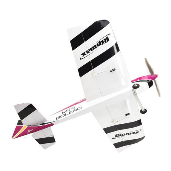
Specification:
Wingspan: 950mm (37.5")
Length: 950mm (37.5")
Flying weight: 870-920g (1Ib 15oz-2lbs 0.5oz)
Radio: 4-5 Channel* Servos: 4x Mini*
*
(Recommendation, not included)
Technische Daten:
Spannweite: 950mm
Länge: 950mm
Fluggewicht: ca. 870-920g
Fernsteuerung: 4...5-Kanal* Servos: 4x Mini*
*
(empfohlen aber nicht enthalten)
Instruction Manual
Bauanleitung
A-ARTF6740
Advertisement

Related Manuals for Ripmax MINI BOLERO


Summary of Contents for Ripmax MINI BOLERO
- Page 1 Instruction Manual Bauanleitung A-ARTF6740 Technische Daten: Specification: Spannweite: 950mm Wingspan: 950mm (37.5”) Length: 950mm (37.5”) Länge: 950mm Fluggewicht: ca. 870-920g Flying weight: 870-920g (1Ib 15oz-2lbs 0.5oz) Radio: 4-5 Channel* Servos: 4x Mini* Fernsteuerung: 4...5-Kanal* Servos: 4x Mini* (Recommendation, not included) (empfohlen aber nicht enthalten)
- Page 2 INSTRUCTIONS / ANLEITUNG...
-
Page 3: General Notices
Ripmax shall not be liable for any loss, consequential loss, damage will increase the risk of injury. Always keep yourself at a or expense arising from the improper use or operation in anyway. -
Page 4: Wichtige Hinweise
Haftungsausschluss: mit sich drehenden Teilen in Berührung kommen! Denken Sie auch an Ihre Haustiere! Ripmax Produkte sind häufig nur ein Teil einer ganzen Funktionskette. Diese Funktionskette, wie auch die Einhaltung der Fliegen Sie grundsätzlich, ob mit Modellflugzeugen-, Montage und Betriebsanleitung als auch die Bedingungen und Hubschraubern- oder Multicoptern, nie in Augenhöhe... - Page 5 INSTRUCTIONS / ANLEITUNG Contents / Inhalt Parts List: Take a moment to identify each of the par ts supplied and read through these Wings instructions before commencing assembly. Fuselage Tailplane Rudder Canopy Fibreglass cowl Wing spar Spinner Control rods Accessories Teileliste: Tragfläche Rumpf...
- Page 6 INSTRUCTIONS / ANLEITUNG Stage Schritt The wings and ailerons are supplied with the hinges loosely fitted, ready for installation. Remove both ailerons and ensure that the hinges are inserted mid-way in their slots. Using thin cyano, pour a couple of drops onto each hinge – above and below –...
- Page 7 INSTRUCTIONS / ANLEITUNG Stage Schritt Fit a 200mm extension lead to your aileron servo. It is a good idea to use a lead-lock, a turn of insulation tape or heat shrink tube over the joint for additional security. Carefully tape the end of each servo lead to the length of thread installed in the wing.
- Page 8 INSTRUCTIONS / ANLEITUNG Stage Schritt Locate an aileron pushrod and attach a nylon clevis to the end, then clip the pushrod to a control horn. The horns need to be positioned inline with the aileron servo output arm, use the pushrod as a guide remembering to align the row of holes in the horn with the hinge line.
- Page 9 INSTRUCTIONS / ANLEITUNG Stage Schritt Remove and slide the aileron servo horn over the wire and re-fit to the servo. Fit a moulded keeper and snap it onto the pushrod to retain it as shown. Schieben Sie das Querruder Servohorn über den Draht, befesti- gen Sie dies wieder am Servo.
- Page 10 INSTRUCTIONS / ANLEITUNG Stage Schritt Cut the film away from the wing mounting holes, the spar hole and the wire hole on both sides of the fuselage. Entfernen Sie die Folie über den Flächenbefestigungen sowie für die Befestigung auf beiden Seiten des Rumpfes. Stage Schritt Locate the slots at the rear of the fuselage for the tailplane and...
- Page 11 INSTRUCTIONS / ANLEITUNG Stage Schritt Remove the tailplane and cut away the covering from just inside the marked lines to give a film-free surface for the glue to bond. IMPORTANT: Ensure that only the film is cut - not the tailplane as this will seriously weaken the structure.
- Page 12 INSTRUCTIONS / ANLEITUNG Stage Schritt Add some slow setting epoxy to the elevator slots and proceed to the next step before it sets. Geben Sie etwas langsam härtendes Epoxydharz in dieHöhenruderschlitze und gehen Sie zum nächsten Schritt. Stage Schritt Protecting the rear of the tailplane with a strip of masking tape, apply epoxy to one half of the wire elevator joiner and force it into the corresponding slot and hole in the elevator half.
- Page 13 INSTRUCTIONS / ANLEITUNG Stage Schritt Insert three hinges into the rudder, ensuring they are located midway in their slots. Using thin cyano, pour a couple of drops onto each hinge - above and below - ensuring the glue soaks into the hinge and the surrounding wood.
- Page 14 INSTRUCTIONS / ANLEITUNG Stage Schritt Locate the pushrod exit slots on each side of the fuselage under the tailplane for the rudder and in front of the tailplane for the elevator. Use a sharp knife to carefully remove the covering from the slots.
- Page 15 INSTRUCTIONS / ANLEITUNG INSTRUCTIONS / ANLEITUNG Stage Schritt With the elevator and elevator servo centred, mark the point that the pushrod passes the servo output arm. Mit dem ausgemittelten Höhenruder und Servo markieren Sie die Position des Gestänges an dem Punkt, wo es den Servoarm passiert Stage Schritt...
- Page 16 INSTRUCTIONS / ANLEITUNG Stage Schritt Ensure all controls move freely through the entire range of travel without binding. Refit the servo output arm retaining screws when completed. Vergewissern Sie sich dass alle Ruderbewegungen, über den gesamten Ruderweg frei beweglich sind. Wenn Sie alles abgeschlossen haben, schrauben Sie die Servohörner fest.
- Page 17 INSTRUCTIONS / ANLEITUNG Stage Schritt Locate the pre-bent wire tail skid, then make a mark 20mm forward of the rear of the fuselage and drill a 1mm hole in the middle of the fuselage as shown. Glue the tail skid into the hole. Nehmen Sie den vorgebogenen Hecksporn.
- Page 18 INSTRUCTIONS / ANLEITUNG Stage Schritt To set the cowl/spinner clearance, attach some foam tape to the back of the backplate to act as a spacer. Position the cowl and bolt on the spinner back plate to get the clearance correct. Zum Einstellen des Abstandes der Motorhaube und des Spinners befestigen Sie einige Schaumstoffbänder an der Rückseite der Spinnerplatte.
- Page 19 INSTRUCTIONS / ANLEITUNG Stage Schritt The wings slide into position over a fibreglass tube and are secured in place with two plastic thumb screws. Take care not to trap the servo leads when securing. Schieben Sie die Tragflächen über das Fiberglasrohr und sichern Sie diese mit den Kunststoffschrauben.
- Page 20 Do not miss out this step in completing your Mini Bolero. Der Schwerpunkt des Modells (C/G oder Balance Point) sollte bei 85-95mm liegen.
-
Page 21: Spare Par Ts / Ersatzteile
Ruder ohne Widerstand frei bewegen können, und sich nicht verwinden. Spare Par ts / Ersatzteile Spare parts are available for the Mini Bolero from all Ripmax stocked model shops. In case of any difficulty, any product queries, or to locate your local Ripmax stockist, please visit www.ripmax.com Ersatzteile sind für den Mini Bolero in allen Ripmax Modellfachgeschäften verfügbar. - Page 22 Flying the Mini Bolero/ Den Mini BoleroFliegen The Mini Bolero is a 3D Parkflyer and is a joy to fly, although we do not recommend flying it on windy days due to the small size and relatively the large wing area as it can get easily blown around, 0-10mph is best. Using the recommended 3S power system you will have well over a 1:1 power to weight ratio, a 3S 1300mAh battery is the best balance of power and weight as bigger batteries increase the wing loading more than necessary.
- Page 23 INSTRUCTIONS / ANLEITUNG...
- Page 24 Copying or reproduction – even in parts – requires schriftlicher Genehmigung der Ripmax Ltd. the written permission of Ripmax Ltd. Made in China Manufactured for and distributed to your local model shop by: Ripmax Ltd., Unit 1, Ingersoll House, Delamare Road, Cheshunt, Herts., EN8 9SL. United Kingdom.
Need help?
Do you have a question about the MINI BOLERO and is the answer not in the manual?
Questions and answers