Advertisement
Quick Links
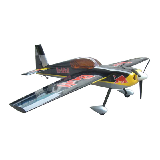
Wing Span:70.8in/1800mm;
Wing Area:62sq.dm;
Length:66.1in/1680mm;
CAUTION : this plane is not a toy!
Before use , please carefully read this manual.
●First-time builders should seek advice from people having building
experience in order to assemble the model correctly and to produce its
performance to full extent .
●Assemble this kit only in places out of children's reach!
●Take enough safety percautions prior to operating this model.
You are responsible for this model's assembly and safe operation!
●Always keep this instruction manual ready at hand for quick
reference,even after completing the assembly.
Flying Weight:3800g;
Radio:6channels 5-6servos;
Engine:26-30CC GAS;
P1
Advertisement

Related Manuals for Turnigy EDGE-540


Summary of Contents for Turnigy EDGE-540
- Page 1 Wing Span:70.8in/1800mm; Flying Weight:3800g; Wing Area:62sq.dm; Radio:6channels 5-6servos; Length:66.1in/1680mm; Engine:26-30CC GAS; CAUTION : this plane is not a toy! Before use , please carefully read this manual. ●First-time builders should seek advice from people having building experience in order to assemble the model correctly and to produce its performance to full extent .
-
Page 2: Kit Contents
KIT CONTENTS MAIN WINGS Connect the aileron and main Glue wing with horns. - Page 3 Cut away covering film for the servo. Measure the length of the extention . Pull out the extention from the rib of the main wing.
- Page 4 Install the tri-horn and servo arm with pushrod as shown. Find out the holes in each sides of fuselage, then cut the film. Nylon Pull out the servo extention Screw as shown.
-
Page 5: Main Landing Gear
MAIN LANDING GEAR Install the wheel with screw and collars as shown. Fixup the wheel to the landing gear by screw. Use two TP screws to fix the wheel cover to the landing gear. - Page 6 Install the main landing gear on the bottom of the fuselage. Fixup 3 screws as shown. ELEVATOR AND RUDDER Connect the elevator and stabilizer with horns and U steel wire. Connect the rudder and the vertifin with horns.
- Page 7 Find and cut the hole for elevator and also the servo holes. Cut away the film along the edges, and glow the stabilizer to the fuselage. Cut the rudder film along the edges, and glue the rudder to the fuselage.
- Page 8 Securely glue up and soaked up the hinge with AB glue. Glue the rudder to the fuselage. Install the elevator servo as shown.
- Page 9 Tighten the second loop through the brass swage tube. Crimp the brass tube with a crimping tool or pliers. Connect the parts as shown.
-
Page 10: Tail Wheel
Push rods Rudder servo arm Connect the control horn to the linkage of the servo. TAIL WHEEL Bend the tail landing gear to fit for the rudder and insert it into the rudder. - Page 11 Glow the tail landing gear to the rudder securely. Install the tail wheel, and fasten the presser of the tail wheel to the stabilizer by screws. Place the hatch. Use two screws to secure it firmly.
- Page 12 Another method for the rudder servo installation Install the ball linkege connector.Calculate the length proportion between the servo arm and the horn.Rotate the ball linkage connector to an appropriate position. ENGINE Gather the engine and spare parts as shown.
- Page 13 The finished picture as shown. Install the DLE 30CC as shown. Pay attention to:you have DLE and MLD for choice.
- Page 15 CG POSITION & CONTROL THROWS...
- Page 16 FINISHED PICTURE...
Need help?
Do you have a question about the EDGE-540 and is the answer not in the manual?
Questions and answers