Advertisement
Quick Links
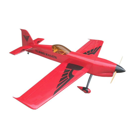
Wing Span:74.8in/1900mm;
Wing Area:68sq.dm;
Length:72.8in/1850mm;
CAUTION : this plane is not a toy!
Before use , please carefully read this manual.
●First-time builders should seek advice from people having building
experience in order to assemble the model correctly and to produce its
performance to full extent .
●Assemble this kit only in places out of children's reach!
●Take enough safety percautions prior to operating this model.
You are responsible for this model's assembly and safe operation!
●Always keep this instruction manual ready at hand for quick
reference,even after completing the assembly.
Flying Weight:5200-5500g;
Radio:6channels 6servos;
Engine:30-35CC GAS;
P1
Advertisement

Related Manuals for Turnigy Turbo Raven 30-35CC


Summary of Contents for Turnigy Turbo Raven 30-35CC
- Page 1 Wing Span:74.8in/1900mm; Flying Weight:5200-5500g; Wing Area:68sq.dm; Radio:6channels 6servos; Length:72.8in/1850mm; Engine:30-35CC GAS; CAUTION : this plane is not a toy! Before use , please carefully read this manual. ●First-time builders should seek advice from people having building experience in order to assemble the model correctly and to produce its performance to full extent .
-
Page 2: Main Wings
MAIN WINGS Connect the aileron and main wing with horns. Cut away covering film for the servo. Install Servo Arms... - Page 3 Find out the holes in each sides of fuselage, then remove the covering. Connect the main wings and the fuselage with joiner. Also pull the extension into the fuselage. Plastic Fixup the wings with plastic bolt bolts on both sides.
-
Page 4: Main Landing Gear
MAIN LANDING GEAR Gather the wheels,axles and collars as shown. Carbon Fiber Landing gear Wheel Pants Permanently tighten the axle to the gear strut by wrenches. - Page 5 Install wheel pants with two mounting bolts. Install the main landing gear on the bottom of the fuselage. Pay attention to:we have CB and AL landing gear for choice. ELEVATOR AND RUDDER Find out the holes on each sides of tail fuselage. Insert the stabilizer into the prepared hole.
- Page 6 Elevator assemblies. Install elevator servos on each sides of tailplane. Elevator pushrod. Rudder assemblies.
-
Page 7: Tail Wheel
Rudder pushrod. Push rods Rudder servo arm TAIL WHEEL ●Ensure the servo doesn't bind at center or at either end point. Drill holes in the hardwood tail wheel mount and install the blind nut through the opening in the rear of the fuse. Install the mounting screw for the tail wheel. - Page 8 Install the tailwheel as shown. Install the hatch over the opening in the rear of the stabilizer with 4 screws. ENGINE Install the DLE 30CC as shown.
- Page 9 FUEL TANK Install the trottle servo as shown. Fuel pipe...
- Page 10 Place the hatch. Use two screws to secure it firmly. COWLING Mounting the cowling by wood screws.
- Page 11 CG POSITION & CONTROL THROWS...
Need help?
Do you have a question about the Turbo Raven 30-35CC and is the answer not in the manual?
Questions and answers