Advertisement
Quick Links
Application Engineering Bulletin
AE-1313
GUIDELINES TO USING A THREE PHASE VOLTAGE MONITOR
INTRODUCTION
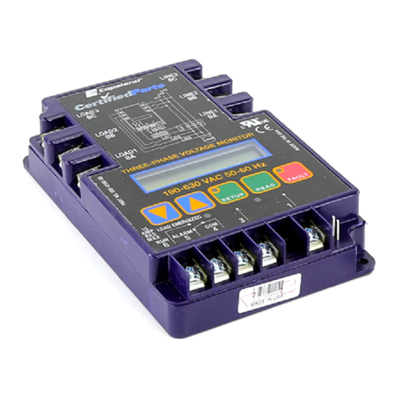
A phase monitor can be used with any three phase
motor. A monitor such as the Copeland 085-0160-00 is
recommended for monitoring remote locations or envi-
ronments with a history of adverse voltage fluctuations.
Many compressor failures are caused by an intoler-
able line voltage. These voltage variations can have
many different sources such as contactor failure or
ground interference. Irrelevant of the cause, compres-
sor failures due to voltage fluctuations may be pre-
vented. Although the voltage fluctuations themselves
may be inevitable, actual motor damage can usually be
averted.
FAULT DETECTION
The phase monitor checks for critical faults
•Phase loss
•Phase reversal
•High voltage
•Low voltage
•Voltage unbalance
A phase reversal is very damaging to phase sensi-
tive machines such as scroll compressors, screw com-
pressors, and fan motors. A phase loss will cause
excessively high current resulting in high temperatures
in the other two motor phases. High voltage causes
excessive temps inside the motor. Low voltage in-
creases the slip of the motor producing excess heat.
Phase unbalance is when the voltage to each phase is
not equal, as a result, some windings do more work than
others. This causes excessive heat.
© 2000 Copeland Corporation
Printed in U.S.A.
ELECTRICAL WIRING SET UP
For single contactor systems, connect the monitor
to the three phase power supply as shown in Figure 1 .
For a part winding start with two contactors and two
phase monitors, connect the monitors as shown in
Figure 2.
*
*1 amp fuse recommended
Voltage Wiring for Three Phase Line Monitors
1
Copeland 10-1313
10-1313
10-1313
Issued September, 2000
*
Figure 1
Advertisement

Related Manuals for Copeland 085-0160-00


Summary of Contents for Copeland 085-0160-00
- Page 1 For single contactor systems, connect the monitor to the three phase power supply as shown in Figure 1 . motor. A monitor such as the Copeland 085-0160-00 is recommended for monitoring remote locations or envi- For a part winding start with two contactors and two ronments with a history of adverse voltage fluctuations.
- Page 2 Copeland 10-1313 Part Winding Start (PWS) For 3-Phase Monitors Figure 2 © 2000 Copeland Corporation © 2000 Copeland Corporation Printed in U.S.A. Printed in U.S.A.
- Page 3 Figure 3 Control Mode Factory setting: off Adjustment not permitted when used on the Copeland compressors. PARAMETER SETTINGS Note: It may be necessary to clear any faults that Changes to parameter settings may result in less occurred during initial power up.
- Page 4 The amount of time between the load and OFF de-energizing and re-energizing may be to short. Press set up to enter time phase loss/rev (Delay on break) mode. Use the arrow up to lengthen the delay. © 2000 Copeland Corporation Printed in U.S.A.
Need help?
Do you have a question about the 085-0160-00 and is the answer not in the manual?
Questions and answers