Table of Contents
Advertisement
Advertisement
Table of Contents

Subscribe to Our Youtube Channel
Related Manuals for Zodiac Cybernaut NT


Summary of Contents for Zodiac Cybernaut NT
- Page 1 CYBERNAUT NT © ZPCE - EXPERT PARTNER PROGRAM 2013-2014...
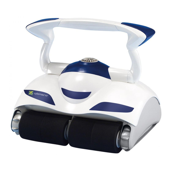
- Page 2 CYBERNAUT NT The product + 3 motor cleaners 3 motor cleaners 1 motor suction pump - propulsion and cleaning 2 drive motors Forward and reverse movements Rotations © ZPCE - EXPERT PARTNER PROGRAM 2013-2014...
- Page 3 CYBERNAUT NT The product + Movement Movement Gear transmission Patented system "IS Track System" © ZPCE - EXPERT PARTNER PROGRAM 2013-2014...
- Page 4 CYBERNAUT NT The product + Automatic cleaning Automatic cleaning Pre-programmed or remotely controlled (caddy) Custom programming Custom programming Time and movement calculated depending on the size and the shape of the pool © ZPCE - EXPERT PARTNER PROGRAM 2013-2014...
- Page 5 CYBERNAUT NT The product + Reliable - ABS Materials - Protection bumper Protection bumper 3 safety features - Out of the water - Beach - Jamming Digital display control box Accessible from the transport caddy 2 year guarantee © ZPCE - EXPERT PARTNER PROGRAM 2013-2014...
- Page 6 CYBERNAUT NT Programming Programming Using the control box Possibility of adapting a programmable timer © ZPCE - EXPERT PARTNER PROGRAM 2013-2014...
- Page 7 CYBERNAUT NT Only programme once! Only programme once! Only on first use following 4 Selection of the parameters: Shape Length Width height of the sides a specific a specific The cleaner automatically calculates The cleaner automatically calculates sequence of movements…...
- Page 8 CYBERNAUT NT Accessories Included in the packaging Included in the packaging FOAM Brushes Very fine filtering Available as options Available as options BLADE, FOAM, PVA brushes BLADE, FOAM, PVA brushes Fine filtering Protection cover...
- Page 9 CYBERNAUT NT Installation principle Easy electric connection Easy electric connection Connect the cleaner to the control box Connect the control box to the mains © ZPCE - EXPERT PARTNER PROGRAM 2013-2014...
- Page 10 CYBERNAUT NT Installation principle Technical specificities Technical specificities CYBERNAUT NT CYBERNAUT NT Control box power supply 230 V 50 Hz Robot power supply Robot power supply 30 V DC 30 V DC Absorbed power 150 W max Pump flow 20 m³/hr ³/h...
- Page 11 CYBERNAUT NT Diagnosis assistance Disconnect the control box from the Disconnect the control box from the mains before any interventions! © ZPCE - EXPERT PARTNER PROGRAM 2013-2014...
- Page 12 CYBERNAUT NT Diagnosis assistance Full Diagnostic Box (Cybernaut NT > 2010) Full Diagnostic Box (Cybernaut NT > 2010) Used to quickly test: -The control box card/keyboard power supply card/keyboard power supply -The motor block: motorisation function / sensors Remote motorisation function / sensors Remote (Vortex™...
- Page 13 CYBERNAUT NT Diagnosis assistance Inefficient filtering - low adherence ffi i t filt The filtering seems weak and debris comes out via the The filtering seems weak and debris comes out via the propeller Check: The filter bag g The casing valves...
- Page 14 CYBERNAUT NT Diagnosis assistance Difficulties in climbing the sides Difficulties in climbing the sides The cleaner moves forwards and backwards but has diffi difficulties climbing the pool sides or does not climb at all l id t li b t ll...
- Page 15 CYBERNAUT NT Diagnosis assistance The cleaner rises above the water line The cleaner comes too far above the water line and sucks in air Re-immerse the cleaner Press the foam and overturn the cleaner to remove the air from the filter bag g...
- Page 16 CYBERNAUT NT Diagnosis assistance The cleaner tips backwards The cleaner tips backwards The cleaner tips backwards at the foot of the wall The cleaner tips backwards at the foot of the wall The propeller is broken or The suction system is not...
- Page 17 CYBERNAUT NT Diagnosis assistance Movements are not straight i ht The cleaner does not move in a straight line and drifts A foreign body is The transmission The floating jammed in the is worn or a cable is stretched cable is stretched...
- Page 18 CYBERNAUT NT Diagnosis assistance No movement – No suction Check the display After having disconnected the cleaner from the control box, does the display stay off? Check the Replace Check that "Privileged" Privileged check the cable check the cable th CPU the CPU card ...
- Page 19 CYBERNAUT NT Diagnosis assistance No rotation when running in automatic No rotation when running in automatic Check the angle sensor Check the "Privileged" mode: List of EE codes List of EE codes Cyber NT access Consumption values Is the angle sensor operating normally?
- Page 20 CYBERNAUT NT Diagnosis assistance EE safety codes Code Problems Solutions Pump short circuit Short circuit drive motor 1 Short circuit drive motor 1 Request post sales service (opposite the cable) Short circuit drive motor 2 (cable side) (cable side) Pump overconsumption Check the propeller and flow guide Drive motor 1 overconsumption (opposite the cable) Check the appropriate transmission cartridge Drive motor 2 overconsumption (cable side) Drive motor 2 overconsumption (cable side) Pump under consumption (out of water) Purge the air from the cleaner Otherwise it is a pump problem Otherwise it is a pump problem...
- Page 21 CYBERNAUT NT Diagnosis assistance EE safety codes Cleaners <=2009 Cleaners < 2009 2010 Cleaners 2010 Cleaners To exit from the error message, press the left and right arrows at the same time © ZPCE - EXPERT PARTNER PROGRAM 2013-2014...
- Page 22 CYBERNAUT NT Diagnosis assistance P i il Privileged mode Access to information on the motor block consumption and the angle sensor angle sensor. Conditions required to take the measurements: Cleaner on the pool bottom (Water T° > 10°C) and not rotating...
- Page 23 CYBERNAUT NT Diagnosis assistance Angle sensor test Angle sensor test © ZPCE - EXPERT PARTNER PROGRAM 2013-2014...
- Page 24 CYBERNAUT NT Repair procedure Replacing the display card th di Remember to remove the protective film from the screen and the direction of the connector Remove the connector Remove the nuts Remove the nuts Remove the card...
- Page 25 CYBERNAUT NT Repair procedure Removing the handle th h Remove the flow guide Remove the flow guide Pull the left and right clips vertically while pushing the Pull the left and right clips vertically while pushing the decoration locking clip with a screwdriver...
- Page 26 CYBERNAUT NT Repair procedure Removing the flow guide and propeller Removing the flow guide and propeller Remove the flow guide Remove the flow guide Remove the 4 screws Remove the 4 screws decoration Make a small rotation to the Remove the propeller by pulling on it...
- Page 27 CYBERNAUT NT Repair procedure Removing the cable Free the cable Free the cable Unscrew the nut from Unscrew the nut from Disconnect the cable Disconnect the cable the cable gland from the electronic card Loosen the blocking collar Loosen the blocking collar...
- Page 28 CYBERNAUT NT Repair procedure Replacing the transmission cartridge th t t id Remove the cover Remove the cover With the cleaner overturned, Place the cable flat Place the cable flat remove the 4 screws Remove the top screw Remove the 2 side screws...
- Page 29 CYBERNAUT NT Repair procedure Removing the relay box Removing the relay box Remove the 4 screws from the relay box relay box Check the state of the cable, the conductor must not be oxidised (black) © ZPCE - EXPERT PARTNER PROGRAM 2013-2014...
- Page 30 CYBERNAUT NT Repair procedure Cybernaut NT plug 3M Cybernaut NT plug 3M Loosen the nut on the cable gland Remove the blocking screw Remove the plug from the body Check the connections (colour codes) Keyboard connector...
- Page 31 CYBERNAUT NT Repair procedure Replacing the CPU card th CPU Disconnect the 6 power supply wires from the motor block Disconnect the mains 230 V power supply Disconnect the connector from the display card Disconnect the connector from the display card ...
Need help?
Do you have a question about the Cybernaut NT and is the answer not in the manual?
Questions and answers