Sign In
Upload
Manuals
Brands
Tektronix Manuals
Measuring Instruments
TekRanger 2 TFS3031
Tektronix TekRanger 2 TFS3031 Manuals
Manuals and User Guides for Tektronix TekRanger 2 TFS3031. We have
1
Tektronix TekRanger 2 TFS3031 manual available for free PDF download: Service Manual
Tektronix
TekRanger 2 TFS3031
Service Manual
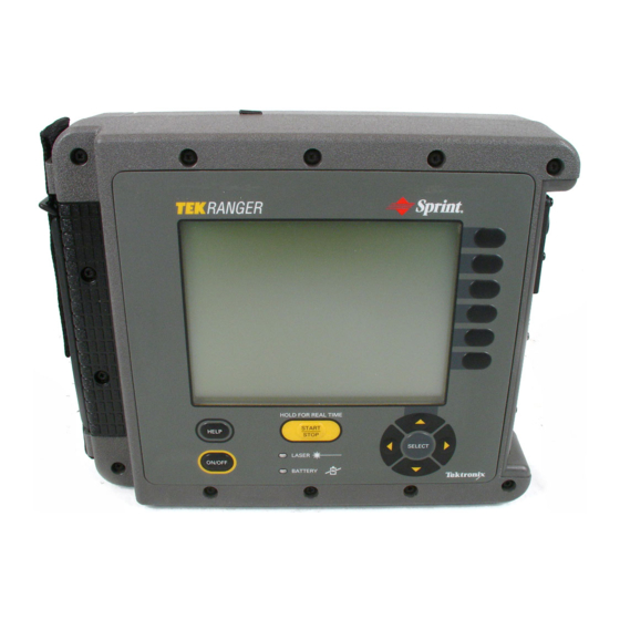
Tektronix TekRanger 2 TFS3031 Service Manual (272 pages)
Mini Optical Time-Domain Reflectometer
Brand:
Tektronix
| Category:
Measuring Instruments
| Size: 4 MB
Table of Contents
Table of Contents
6
List of Figures
9
List of Tables
12
Table 1-10: Horizontal System Distance Span and Range
15
Table 1-11: System Measurement Accuracy (850 Nm Multimode, Options 01 and 03)
15
Table 1-12: Sample Density, Pulsewidth, and Range Combinations
15
Table 1-13: Bandwidth and Transient Characteristics
15
Table 1-14: Optical Signal Characteristics (1300 Nm Multimode, Option 03)
15
Table 1-4: Optical Signal Characteristics (850 Nm Multimode, Options 01 and 03)
15
Table 1-5: Vertical System Measurements (850 Nm Multimode, Options 01 and 03)
15
Table 1-6: Measurement Range
15
Table 1-8: Vertical System Dynamic Range (850 Nm Multimode, Options 01 and 03)
15
Table 1-9: Horizontal System Dead Zone (850 Nm Multimode, Options 01 and 03)
15
General Safety Summary
18
Preface
22
Contacting Tektronix
22
Assumptions
23
Before Servicing
23
What You will Find in this Manual
23
Related Documents
23
Module-Level Service
24
Overview
24
The Functional Modules
24
Table 1-1: TFS3031 Functional Modules
24
Optical Modules
25
Static-Sensitive Components
26
Service Procedure
26
Operator Information
28
Port Functions
28
Figure 1-1: Connector Adapter Installation
29
Updating the Instrument Software
31
Buttons and Keys
32
Keyboard Definitions
33
Table 1-2: Keyboard Text-Entry Functions
33
Table 1-3: Front-Panel Functions
33
Battery Recharging and Replacement
34
Low-Battery Warning
34
When to Recharge the Nicad Battery
34
Power/Charger Adapter
35
Nicad Battery Recharging Procedure
36
Figure 1-2: Nicad Battery Recharging Setup
36
Tips for Maximizing Battery Life
37
Nicad Battery Disconnection, Removal, and Replacement
37
Figure 1-3: Nicad Battery Removal
38
Specifications - Tekranger (Serial Nos. below B052000)
40
Standard 850 Nm Multimode, Options 01 and 03
40
Table 1-7: Single-Event Distance Measurement Repeatability
41
Standard 1300 Nm Multimode, Option 03
44
Standard 1310 Nm Singlemode, Options 04 and 06
50
Standard 1550 Nm Singlemode, Option 06
56
Extended Range 1310 Nm Singlemode, Option 08
62
Extended Range 1550 Nm Singlemode, Option 08
68
Extended Range 1550 Nm Singlemode, Option 09
74
Power
79
Display
79
Size and Weight
79
RS232C Serial Port
80
Parallel Port
80
Keyboard Port
80
Environmental
81
Specifications - Tekranger 2 (Serial Nos. B052000 and Above)
84
Standard 850 Nm Multimode, Options 01 and 03
84
Standard 1300 Nm Multimode, Option 03
89
Standard 1310 Nm Singlemode, Options 04 and 06
95
Standard 1550 Nm Singlemode, Option 06
101
Extended Range 1310/1550 Nm Singlemode, Option 10
106
1625 Nm Singlemode, Option 12
113
Power
118
Display
118
Size and Weight
118
RS232C Serial Port
119
Parallel Port
119
Keyboard Port
119
Environmental
120
Accessories and Options
124
Theory of Operation
130
Figure 2-1: System Block Diagram
130
Theory of Operation
131
Performance Check - Tekranger
134
Introduction
134
Equipment Required for Performance Check
134
Adjustments
135
Test Descriptions
135
Singlemode Event-Detection Test Fixture Build Description
139
Figure 3-1: Singlemode Event-Detection Test Fixture Layout
139
Figure 3-2: Scatter Plot for 50 M Event
141
Singlemode Dynamic-Range Test Fixture Build Description
142
Singlemode Dead-Zone Test Fixture Build Description
142
Figure 3-3: Singlemode Dead-Zone Test Fixture
143
Figure 3-4: Desired OTDR Signature
144
Multimode Dynamic-Range Test Fixture
145
Figure 3-5: Multimode Dynamic-Range Test Fixture
145
Multimode Event-Detection and Dead-Zone Test Fixture
146
Figure 3-6: Multimode Event-Detection and Dead-Zone Test Fixture
146
Figure 3-7: Multimode Event-Detection and Dead-Zone Test Fixture: OTDR Trace
147
Setup
148
Power-On Initialization Check
149
Power/Charger Adapter Check
150
Floppy Disk Drive Check
151
Keyboard Check (Option 19)
152
Singlemode Dynamic Range Check
153
Singlemode Event-Detection Check
154
Singlemode Dead-Zone Check
155
Multimode Dynamic Range Check
157
Multimode Event-Detection Check
158
Multimode Dead-Zone Check
159
Multimode Distance Accuracy Check
161
Performance Check - Tekranger 2
162
Introduction
162
Equipment Required for Performance Check
162
Adjustments
163
Test Descriptions
163
Singlemode Range Test Fixture
167
Figure 4-1: TFS3031 Range Test Fixture
167
Singlemode Dead-Zone Test Fixture
168
Figure 4-2: Singlemode Dead-Zone Test Fixture
168
Singlemode Reflectance Test Fixture
170
Figure 4-3: TFS3031 Singlemode Reflectance Test Fixture
170
Singlemode Loss and Distance Accuracy Test Fixture
171
Figure 4-4: TFS3031 Singlemode Loss and Distance Accuracy Test Fixture
171
Multimode Dynamic-Range Test Fixture
172
Figure 4-5: Multimode Dynamic-Range Test Fixture
172
Multimode Event-Detection and Dead-Zone Test Fixture
173
Figure 4-6: Multimode Event-Detection and Dead-Zone Test Fixture
173
Figure 4-7: Multimode Event-Detection and Dead-Zone Test Fixture: OTDR Trace
174
Figure 4-8: Scatter Plot for 50 M Event
175
Setup
177
Power-On Initialization Check
179
Power/Charger Adapter Check
180
Floppy Disk Drive Check (Option 11)
182
Keyboard Check (Option 19)
183
Singlemode Dynamic Range Check
184
Figure 4-9: Singlemode Dynamic-Range Test Waveform, Longest Pulse Width
185
Figure 4-10: Singlemode Dynamic-Range Check, Longest Pulse Width, Zero Intercept
186
Figure 4-11: Singlemode Dynamic-Range Check, Longest Pulse Width, 98% Noise Level
187
Figure 4-12: Singlemode Dynamic-Range Test Waveform, 500-M Pulse Width
189
Figure 4-13: Singlemode Dynamic-Range Check, 500-M Pulse Width, Zero Intercept
190
Singlemode Dead-Zone Check
196
Singlemode Reflectance-Accuracy Check (Options 04, 06, and 10)
202
Singlemode Distance and Loss Measurement Accuracy Check
205
Multimode Dynamic Range Check
206
Multimode Event-Detection Check
214
Multimode Dead-Zone Check
217
Multimode Distance Accuracy Check
221
Maintenance
222
Fiber Connector
222
Cleaning Materials
222
Cleaning the Laser Output Port
224
Cleaning the Connector Adapter
225
Cleaning the Fiber Connector
226
Disassembly
227
Equipment Required
227
Electrical Modules
229
Mechanical Parts
230
Disassembly Procedure
231
Troubleshooting
247
Static-Sensitive Components
247
No Power-On
247
Error Message Resolution
248
Replaceable Parts
252
Parts Ordering Information
252
Using the Replaceable Parts List
253
Wire and Cable Assemblies
263
Index
266
Advertisement
Advertisement
Related Products
Tektronix Keithley SourceMeter 2470
Tektronix Keithley SourceMeter 2410
Tektronix Keithley 2601B-PULSE
Tektronix KEITHLEY 2614B
Tektronix KEITHLEY 2380-120-60
Tektronix Keithley 2182A
Tektronix 208
Tektronix 2642A
Tektronix 2782
Tektronix KEITHLEY 2182
Tektronix Categories
Test Equipment
Measuring Instruments
Amplifier
Portable Generator
Printer
More Tektronix Manuals
Login
Sign In
OR
Sign in with Facebook
Sign in with Google
Upload manual
Upload from disk
Upload from URL