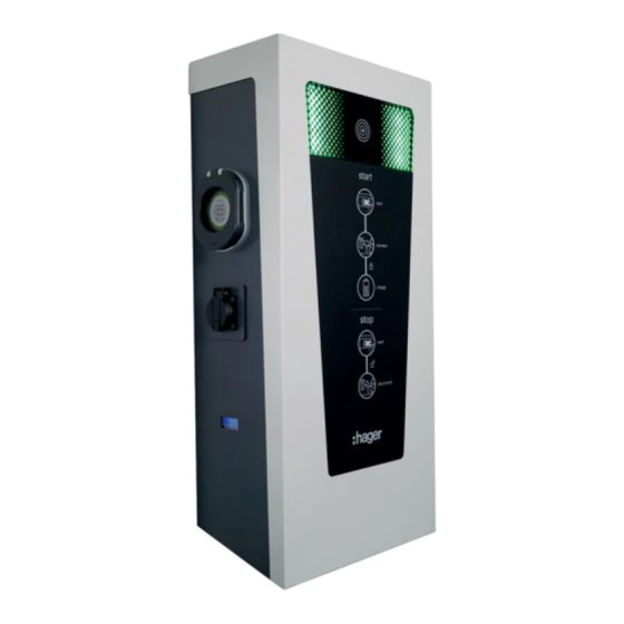
hager XEV6 Series Installation Manual
Hide thumbs
Also See for XEV6 Series:
- Maintenance manual (11 pages) ,
- Quick start manual (8 pages) ,
- Quick start manual (4 pages)
Advertisement
Quick Links
Hager witty park XEV6xx
1. Initial precautions
Please refer to the maintenance manual before starting the installation of the charging station. The device is to be installed only by a professional electrician
fitter according to local applicable installation standards. Conform to SELV installation rules.
2. General description
Socket: Mode 3 Type 2S
Energy meter (version-specific)
1
Installation manual
z
Socket: Mode 2
Optional: base
Strip light
RFID Card Reader
Optional: integration of a modem
The outer casing can be removed
by unscrewing two screws
Optional integration of a protective casing
6LE002957B
Advertisement

Summary of Contents for hager XEV6 Series
- Page 1 Installation manual Hager witty park XEV6xx 1. Initial precautions Please refer to the maintenance manual before starting the installation of the charging station. The device is to be installed only by a professional electrician fitter according to local applicable installation standards. Conform to SELV installation rules.
- Page 2 3. Electrical components of the charging terminal The inner cabinet, depending on the version, comprises the following parts: Contact detection fixed on the contactor TCP/IP Board (version-specific) Controller 1 M3T2S socket (lockable) 3 M3T2S socket (lockable) Controller power supply 2 M2TE socket 4 M2TE socket Circuit breakers Power contactors...
- Page 3 4. Attachment and connection a. Diagrams for wall drilling without wiring space at the rear 4x (not included) 6LE002957B...
- Page 4 b. Diagrams for wall drilling with wiring space at the rear for XEV427 4x (not included) XEV427 ➞ 6LE002957B...
- Page 5 c. Floor mounting diagrams for XEV426 + XEV428 Terminal Installation Area Foundation C20/25, X0 Depth 80 cm Bedding Layer XEV428 5 cm, C8/10 XEV426 In case of a chemical seal, use threaded rods with diameter of 12 mm. ➞ ➞ ➞...
- Page 6 The terminal MUST be mounted on its base BEFORE attaching the vector cabinet. The equipotential bonding must be established between the terminal, foot and base. * Earthing point to connect to the earth system 6LE002957B...
-
Page 7: Electrical Installation
5. Electrical installation a. Power supply Wiring diagram (version-specific) -X1: 1/2 L1 L2 L3 -X0:1 N LST -X0:3 N LST -X2: 3/4 L1 L2 L3 Three-phase power MZ203 trigger circuit MZ203 Trigger circuit Three-phase power Controller power supply 1 connection connection supply 2 supply... - Page 8 c. Protections Single-phase MZ203 40 A 40 A C curve C curve 30 mA 30 mA type A type A protections protections for the for the controller controller supply supply Three-phase 40 A 40 A MZ203 C curve C curve 30 mA 30 mA type B...
- Page 9 d. Earthing quality according to the ZE READY 1.2 label TN or TT neutral point connection neutral neutral neutral neutral point point point point connection connection connection Max. 5 stations on 1 earthing connection Max. 50 Ω for Interconnection the 5 Max.
- Page 10 6. Configuration of the terminal a. Controller’s configuration file Use the ‘b1237 global.cfg’ file to configure the controller. Turn on the station, wait at least 1 minute before inserting the key, then wait 5 seconds before removing it. Rename the ‘b1237 diagnose.txt’ file to ‘b1237 global.cfg’...
- Page 11 b. Settings (cont.) dhcp 0 Inactive DHCP addressing Depending on the network configuration 1 Active DHCP addressing ip_addr xxx.xxx.xxx.xxx IP Address Depending on the network configuration subnet_mask xxx.xxx.xxx.xxx Subnet mask Depending on the network configuration gateway xxx.xxx.xxx.xxx Gateway Depending on the network configuration dns1 xxx.xxx.xxx.xxx 1st DNS address...
- Page 12 Creation/modification of a whitelist from the badges The terminal should be in the local access control mode (Access_control=1) with a blank USB key in the controller slot. Scan the desired badges individually (wait for the station to stop blinking before scanning the next badge) and scan the last one twice in a row.
- Page 13 e. Charging deferred by an external signal of 230Vac System Pin 50 and 51 The switch must be set to ‘Sun’. Connect the 230 VAC load management signal to the station’s PINs 50 and 51. Edit the ‘b1237 global.cfg’ file as follows: If 1 Partial charging override If 2 Full charging override Note: in this case, any charge that has started will stop as soon as the external 230Vac signal appears and will resume if it disappears.
- Page 14 7. HMI Status Server querying Slowly flashing blue Charging management - lowering the power during a session Undulating blue Charging management - External signal - temporary charge stop (D/N INPUT) Undulating blue Extended charging (interrupted charging, lowered power, etc.) Undulating blue Charging management - load shedding during a session Undulating blue Fault - Power failure...
-
Page 15: Electrical Maintenance
8. Malfunction Number of Type of fault Cause pulses Charging cable fault Defective or incompatible cable (13A) Indicator light Defective communication Defective cable - short-circuit during communication flashing Electric vehicle is overcharged The EV does not comply with the power limit set by the station. -
Page 16: Technical Data
USB key provided with the terminals and on the Hager website of your country. Correct Disposal of this product (Waste Electrical &...


Need help?
Do you have a question about the XEV6 Series and is the answer not in the manual?
Questions and answers