Table of Contents
Advertisement
Available languages
Available languages
Quick Links
Advertisement
Table of Contents

Subscribe to Our Youtube Channel
Related Manuals for Hazet 4934-3478/11


Summary of Contents for Hazet 4934-3478/11
- Page 1 H A Z E T- W E R K HÖCHSTE TECHNOLOGIE IN DER WERKZEUGFERTIGUNG SEIT 1868 HIGHEST TECHNOLOGY IN TOOL MANUFACTURE SINCE 1868 4934-3478/11 4934-3482/6 Betriebsanleitung Radnaben-Werkzeug Satz Operating Instructions Wheel Hub Bearing Tool Set...
-
Page 2: Table Of Contents
Disposal Ursprungsprache deutsch – original language: German – Langue d’origine: allemand HAZET-WERK - Hermann Zerver GmbH & Co. KG } 10 04 61 • D-42804 Remscheid • Germany • [ +49 (0) 21 91 / 7 92-0 \ +49 (0) 21 91 / 7 92-375 (Deutschland) • \ +49 (0) 21 91 / 7 92-400 (International) -
Page 3: Zu Ihrer Information
Hinweise, deren Nichtbeachtung Werkzeug Satz auf. Beschädigungen, Fehlfunktionen • Dieses Werkzeug wurde für bestimmte und/oder den Ausfall des Gerätes An w endungen entwickelt. HAZET weist zur Folge haben. ausdrücklich darauf hin, dass dieses Werkzeug nicht verändert und/oder in einer Weise eingesetzt werden darf, die nicht seinem vorgesehenen Verwendungszweck entspricht. - Page 4 Zu Ihrer Sicherheit 1. Verantwortung des Betreibers • Das RadnabenWerkzeug kann ausschließ lich von Hand betätigt werden. Das Gerät ist zum Zeitpunkt seiner • Jede über die bestimmungsgemäße Verwen Entwicklung und Fertigung nach gel dung hinausgehende und/oder andersar tenden, anerkannten Regeln der tige Verwendung des RadnabenWerkzeug Technik gebaut und gilt als betriebs Satzes ist untersagt und gilt als nicht bestim sicher. Es können vom Gerät jedoch mungsgemäß. Gefahren ausgehen, wenn es von nicht fach • Ansprüche jeglicher Art gegen den Hersteller gerecht ausgebildetem Personal, unsachge und/oder seine Bevollmächtigten wegen mäß oder nicht bestimmungsgemäß, ver Schäden aus nicht bestimmungsgemäßer wendet wird. Jede Person, die mit Arbeiten Verwendung des RadnabenWerkzeug am oder mit dem Gerät beauftragt ist, muss...
-
Page 5: Zu Ihrer Sicherheit
Zu Ihrer Sicherheit 3. gefahren die vom gerät ausgehen Vor jeder Benutzung ist der Radnaben Werkzeug Satz auf seine volle Funk tions f ähig k eit prüfen. Ist die Funk t ions f ähigkeit nach dem Ergebnis dieser Prüfung nicht gewährleistet oder wer den Schäden festgestellt, darf das Radnaben Werkzeug nicht verwendet werden. Ist die volle Funktions f ähigkeit nicht gegeben und das RadnabenWerkzeug wird dennoch verwen... -
Page 6: Aufbau Und Funktion
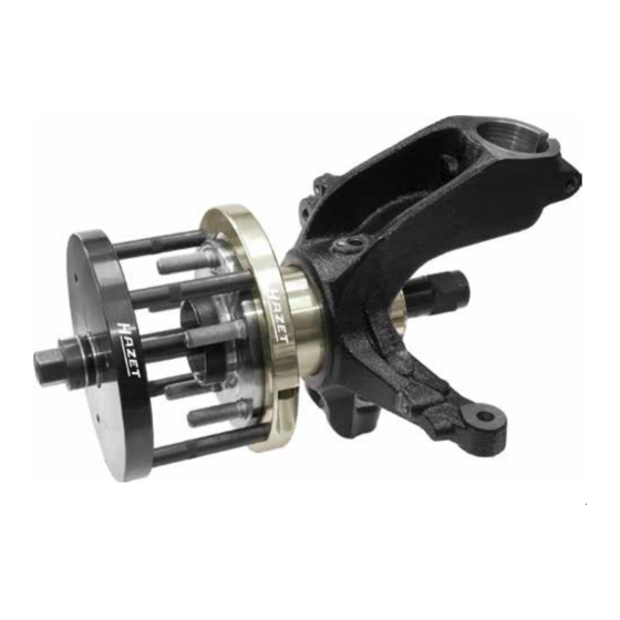
Aufbau und Funktion 1. Technische Daten / Geräteelemente Einzelteile oder oder oder 2. Lieferumfang 4934-3478/11 für Radlager d 78 mm Bezeichnung Maß 4934-7801 Druckplatte 169 mm 4934-7802 Druckscheibe zum Ausbauen 48 mm 4934-8503 Druckbolzen 12 mm 4934-7804 Stützringhälften zum Ausbauen 171 mm 4934-7805 Stützringhälften zum Einbauen 171 mm 4934-7806 Druckscheibe zum Einbauen 80 mm Zylinderschrauben DIN EN ISo 4762 M 8 x 35 Güte 8.8 M 8 x 35... - Page 7 Aufbau und Funktion 3. Anwendung Radnaben ausbauen • Die 4 Druckbolzen F in die Aufnahmebohrungen der Druckplatte E einstecken. Die Radnabe so drehen, dass ein Stehbolzen auf 12:00 Uhr steht. • Die 2 Stützringhälften B seitlich zwischen die Radnabenflanschunterseite und das Lager gehäuse (Achskörper) einschieben und mit den 2 Zylinderschrauben M 8x35 fest verschrauben. Danach den montierten Stützring um 180° zum Radnabenflansch verdrehen, so dass sich die 2 Axialzapfen a auf den Innenflächen der Stehbolzenköpfe c abstützen. Bei Betätigung nicht in die Vorrichtung greifen! Vor jedem Gebrauch die Gewindespindel 4930-1 fetten!
- Page 8 Aufbau und Funktion Zylinderschraube M 8 x 35 49302 49301 • Die Druckscheibe D auf die Spindelmutter 49302 aufstecken. • Die Gewindespindel 49301 durch die Druckplatte E durchstecken. • Die Gewindespindel 49301 mit der Druckplatte E und den 4 eingesteckten Druckbolzen F von außen auf die Radnaben/Lagereinheit so aufsetzen, dass die Druckbolzen F sich in die Vertiefung b des Stützrings B stirnseitig abstützen. Gleichzeitig die Druckscheibe D mit der Spindelmutter 49302 in die Lagerge h äuse i nnenseite einführen und die Gewindespindel 49301 in die Spindelmutter 49302 eindrehen.
- Page 9 Aufbau und Funktion Radnaben/ Lagereinheit einbauen Wichtig: Vor der Montage den Lagersitz reinigen. Radlager und Sitz ausreichend einfetten. Spindel und Spindelmutter ebenfalls ausreichend fetten. Zylinderschraube M 8 x 35 49302 49301 • Die 4 Druckbolzen F in die Aufnahmebohrungen der Druckplatte E einstecken. • Die Stützringhälften A seitlich zwischen die Radnabenflanschunterseite einschieben und mit den 2 Zylinderschrauben M8 x 35 fest verschrauben. • Die Gewindespindel 49301 mit der Druckplatte E und den 4 eingesteckten Druckbolzen F von außen auf die Radnaben/Lagereinheit so aufsetzen, dass die Druckbolzen F sich in den Vertiefungen b des Stützringes A stirnseitig abstützen.
-
Page 10: Wartung Und Pflege
Garantie, Service, Schadenersatz und lich durch Fachpersonal vorzunehmen. Haftpflichtansprüche gegen den Hersteller Ihr Ansprechpartner für: oder seine Beauftragten, Händler und • Gewährleistung Vertreter. • Wartung und Instandsetzung ist der HAZETPartner vor Ort oder das HAZET ServiceCenter servicecenter@hazet.de Aufbewahrung und Lagerung 1. Aufbewahrung / Lagerung Das gerät ist unter folgenden Bedingungen zu lagern und aufzu- bewahren: • Gerät nicht im Freien aufbewahren. -
Page 11: For Your Information
• HAZET will not be liable for any injuries to persons or damage to property originating from improper application, misuse of the tool set or a disregard of the safety instructions. -
Page 12: For Your Safety
For Your Safety 1. owner’s Liability • Any claims against the manufacturer and/ or its authorized agents because of damage This tool set was developed and man caused by improper use of the tool set will ufactured according to the technical be void. norms and standards valid at the time • Any personal injury or material losses caused and is considered to be operationally reliable. by improper use are the sole responsibility Nevertheless, the tool set can present a dan of the owner. ger when it is not used as intended or in an • Prior to each use lubricate the threaded inappropriate way by nonqualified personnel. spindle 49301. Please make sure that any person using this tool set or carrying out maintenance work reads these operating instructions carefully and understands fully all information given, before using the tool. • During operation of the threaded spindle • Keep the operating instructions together do not reach into the extractor device oth... - Page 13 For Your Safety 3. Dangers emanating from the tool Before each use, check the tool set for full functional efficiency. Do not use the tool set if its functional efficiency cannot be ensured or if damage is detected. If the tool set is used, when it is not in full working order, you risk severe injuries to persons and damage to property. • Full functional efficiency is ensured if: – the device is smoothrunning, – the device is not damaged. • Spare parts may only be used in the intend ed composition (chapter c Design and Function). • Due to the heavy weight of the device, there is a risk of injury during dismounting. While operating the threaded spindle do not reach into the extractor device. Make sure that the device is kept safe. • While operating the tool, wear closefitting protective clothing.
-
Page 14: Design And Function
Design and Function 1. Technical Information / Tool Parts Spare parts or or or 2. Included 4934-3478/11 for wheel bearing d 78 mm Designation Dimens. 4934-7801 Thrust plate 169 mm 4934-7802 Thrust washer for dismounting 48 mm 4934-8503 Thrust pin 12 mm 4934-7804 Thrust ring halves for dismounting 171 mm 4934-7805 Thrust ring halves for assembling 171 mm 4934-7806 Thrust washer for assembling 80 mm Cylinder head screws DIN EN ISo 4762 M 8 x 35 Quality 8.8 M 8 x 35... - Page 15 Design and Function 3. Application Dismounting the wheel hub • Insert the 4 thrust pins F into the receiving holes of the thrust plate E. Turn the wheel hub until one stud bolt is on 12 o’clock position. • Put the 2 thrust ring halves B laterally between the rear side of the wheel hub flange and the bearing housing (axle body) and tighten firmly with the 2 cylinder head screws M 8X35. Turn the installed thrust ring through 180° towards the wheel hub flange. Both axial pins a rest on the inside surfaces of the stud bolt heads c.
- Page 16 Design and Function Cylinder head screw M 8 x 35 49302 49301 • Put the thrust washer D onto the spindle nut 49302. • Put the threaded spindle 49301 through the thrust plate E. • Put the threaded spindle 49301 with the thrust plate E and the 4 inserted thrust pins F from outside onto the the wheel bearing / wheel hub in a way that the thrust pins F rest on the recess b of the thrust ring B. At the same time insert the thrust washer D with the spindle nut 49302 into the interior of the bearing housing and screw the threaded spindle 49301 into the spindle nut 49302. • Once the force closure has been reached, the spindle nut 49302 has to be retained with an assembly tool for nuts and screws (e.g. box wrench).
- Page 17 Design and Function Assembling the wheel hub bearing Important: Prior to installation, make sure to clean the bearing seat. Lubricate wheel bearing and bearing seat sufficiently. Also lubricate spindle and spindle nut sufficiently. Cylinder head screw M 8 x 35 49302 49301 • Put the 4 thrust pins F into the receiving holes of the thrust plate E. • Insert the thrust ring halves A laterally between the rear side of the wheel hub flange and tight en firmly with the 2 cylinder head screws M 8 x 35. • Put the threaded spindle 49301 with the thrust plate E with the 4 thrust pins F from outside onto the the wheel bearing / wheel hub in a way that the thrust pins F rest on the recesses b of the thrust ring A.
-
Page 18: Maintenance And Cleaning
Your contacts for for: tributors and sales representatives. • Warranty • Maintenance and repair are your local HAZET partners Storage 1. Storage The tool has to be stored accord- ing to the following conditions • Do not store the tool outdoors. • Keep the tool in a dry and dustfree place. • Do not expose the tool to liquids or aggres... - Page 19 Notizen / Notes...
- Page 20 HAZET-WERK Hermann Zerver GmbH & Co. KG · } 10 04 61 · D42804 REMSCHEID · GERMANY [ +49 (0) 21 91 / 7 920 · \ +49 (0) 21 91 / 7 92375 · ^ hazet.de · ] info@hazet.de...
Need help?
Do you have a question about the 4934-3478/11 and is the answer not in the manual?
Questions and answers