
Related Manuals for Realtek Ameba1 DEV01


Summary of Contents for Realtek Ameba1 DEV01
- Page 1 Realtek Ameba1 DEV01 User Manual This document define pin out of Ameba DEV. Version 1.8...
-
Page 2: Table Of Contents
Pin function table setup ....................8 Peripheral Descriptions ....................9 Hardware configuration ......................10 CMSIS-DAP ......................... 10 J-Link/JTAG ......................... 10 DAP mode ........................12 Reference electrical schematics .................... 14 Ameba1 DEV01 pin out......................16 Sensor board.......................... 17 March 28, 2016... -
Page 3: Hardware Block Diagram
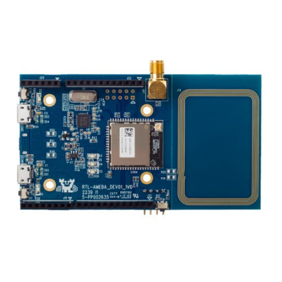
Document Number: UM0058 _______________________________________________________________ 1 Hardware block diagram IC: RTL8195AM Module HDK version: HDK-AM95A03_1V0 DEV HDK version: RTL-AMEBA_DEV01_1v1 NFC Antenna Wi-Fi external Wi-Fi PCB ANT connector Antenna Ameba reset button J-TAG UART RTL8195AM DAP+DC Host +serial port DAP update DAP reset Mode button... -
Page 4: System Requirements
Document Number: UM0058 _______________________________________________________________ 2 System requirements Windows PC (XP, Vista, 7) USB type A to Micro-B USB cable x 1 RS-232 to UART board(debug) x 1, JTAG cable x1 (option) 3 Pin out reference 3.1 Pin out table Con DEV name Pin Net name Con DEV name Pin Net name... -
Page 5: Pin Out Reference
Document Number: UM0058 _______________________________________________________________ 3.2 Pin out reference GPIOA_6 GPIOD_6 GPIOA_7 GPIOD_7 GPIOA_5 DAC_CH0 GPIOD_4 D3/PWM* ADC_CH2 GPIOD_5 ADC_CH1 D4/PWM* GPIOA_4 ADC_CH1 GPIOA_3 GPIOA_2 D8/PWM* GPIOB_4 D9/PWM* GPIOB_5 5VDD GPIOC_0 VDD33 GPIOC_2 GPIOC_3 VDD33 GPIOC_1 GPIOA_1 VDD33 GPIOA_0 GPIOC_4 GPIOE_5 GPIOC_5 GPIOB_3 GPIOB_2... -
Page 6: Pin Connection Table
Document Number: UM0058 _______________________________________________________________ 3.3 Pin connection table VDD33 GPIOB_2 GROUND GPIOB_3 RSVD I2C_SCL GPIOB_0 GPIOC_5 GPIOE_5 I2C_SDA GPIOB_1 GPIOC_4 GPIOA_0 AREF VDD33 GPIOA_1 GROUND RSVD D13/SCK/PWM1 GPIOC_1 IOREF VDD33 D12/MISO/PWM3 GPIOC_3 RESET D11/MOSI/PWM2 GPIOC_2 3.3V VDD33 D10/CS/PWM0 GPIOC_0 5VDD D9/PWM* GPIOB_5 GROUND... -
Page 7: Antenna Hardware Setup
Document Number: UM0058 _______________________________________________________________ 4 Antenna hardware setup I-PEX/U.FL connector: R206 External antenna: R207 PCB antenna: R208 R207 R208 March 28, 2016... -
Page 8: Peripherals Support
Document Number: UM0058 _______________________________________________________________ 5 Peripherals support Debug UART: GPIOB_[0..1] JTAG: GPIOE_[0..4] 5.1 Pin function table setup Multiple functions are supported by group setup. For example: GPIOA_6(Rx), GPIOA_7(Tx), GPIOA_3(RTS) and GPIOA_5(CTS) are used if UART0 function. GPIOA_3(RTS) and GPIOA_5(CTS) can not be used as other functions. -
Page 9: Peripheral Descriptions
Document Number: UM0058 _______________________________________________________________ 5.2 Peripheral Descriptions Baud rate UART_LOG 38400 Hz UART UART0 4 MHz UART2 4 MHz Clock rate SPI0_Master 20.8 MHz SPI0_Slave_TRx 4.1 MHz SPI1_Master 41.6 MHz SPI1_Slave_TRx Clock rate Standard mode 0~100 kb/s Fast mode <400 kb/s High-speed mode <3.4Mb/s March 28, 2016... -
Page 10: Hardware Configuration
Document Number: UM0058 _______________________________________________________________ 6 Hardware configuration 6.1 CMSIS-DAP RTL-AMEBA_DEV01 supports CMSIS-DAP debugger. It requires installing “serial to USB driver”at first. Serial to USB driver can be found in tools\serial_to_usb\mbedWinSerial_16466. Connect board to the PC with micro-USB cable. 6.2 J-Link/JTAG Weld JTAG and log UART connectors to HDK board and connect with pitch 2.54mm 2x5pins connector. - Page 11 Document Number: UM0058 _______________________________________________________________ UART Dupont Line or 2.54mm 2x5 pins connector. Power On(Disable DAP mode) Holding TGT_NRESET button (J24, red-circled) then press Pdn button (J13, blur- circled). Release the button after power on. March 28, 2016...
-
Page 12: Dap Mode
Document Number: UM0058 _______________________________________________________________ 6.3 DAP mode In DAP mode, the DAP firmware can be updated. Holding TGT_NRESET button (J24, red-circled) then press nRESET button (J17, blur-circled). Then the DAP mode window will show up. March 28, 2016... - Page 13 Document Number: UM0058 _______________________________________________________________ DAP window will show up when entering DAP mode. March 28, 2016...
-
Page 14: Reference Electrical Schematics
Document Number: UM0058 _______________________________________________________________ 7 Reference electrical schematics March 28, 2016... - Page 15 Document Number: UM0058 _______________________________________________________________ March 28, 2016...
-
Page 16: Ameba1 Dev01 Pin Out
Document Number: UM0058 _______________________________________________________________ 8 Ameba1 DEV01 pin out March 28, 2016... -
Page 17: Sensor Board
Document Number: UM0058 _______________________________________________________________ 9 Sensor board Extension board: RTL-AMEBA_EXT B2_2V0 March 28, 2016...
Need help?
Do you have a question about the Ameba1 DEV01 and is the answer not in the manual?
Questions and answers